| |
|
|
SkyRanger Build
|
|
6/26/05
I went to Al Fox's place to get the kit. I was hoping to take another flight in his plane but it began to rain right before I reached his place. I got the kit to my house and put it in the garage. I won't start building until after I move to Dallas.
|
|
7/10/05
I finally move to Dallas and start reviewing the manual and DVD.
|
|
7/17/2005 (35 minutes)
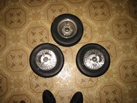
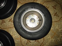
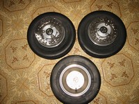
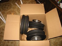
Assembled wheels. I found that there were 2 washers missing, I went ahead and assembled the wheels without tightening the bolts, I put the bolts with the missing washers in the front wheel hub. I'll go to Lowes and get some washers later.
|
|
7/18/2005
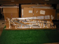
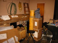
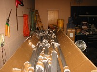
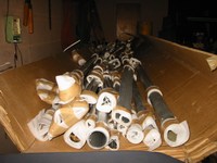
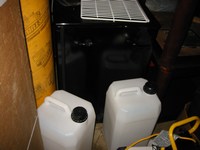
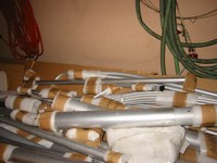
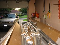
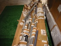
I opened the main box (the 15 foot long one) and began looking and visually sorting out the different parts. I removed the parts for the cabin that I recognized and decided that since I will have a limited amount of space to work in for the next 3 weeks, I will just assemble the cabin and everything forward of the rear fuselage and leave the rear fuselage for later. Upon further inspection of the parts I found a 912 mount, I continued to look through the kit hoping I would find a 582 mount also but to no avail. I will have to call Al to see when I can get a 582 mount to replace the 912 mount. Until then I will try to complete as much of the kit as I can without the mount.
|
|
7/19/2005 (3 hours 35 minutes)
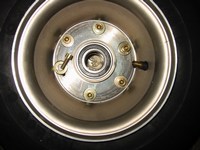
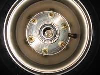
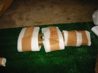
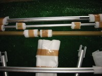
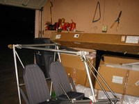
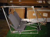
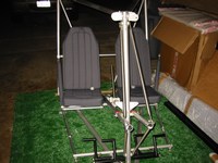
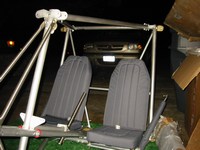
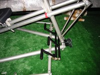
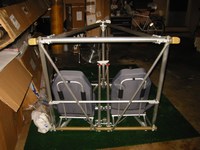
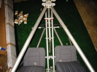
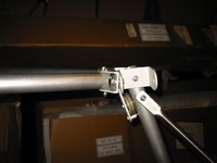
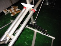
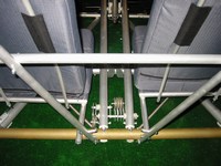
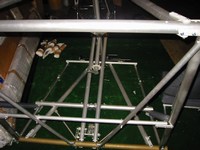
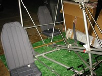
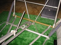
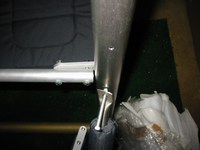
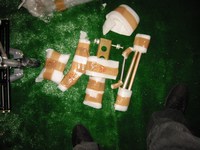
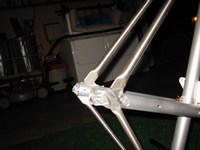
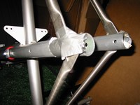
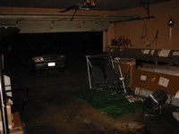
I went to Lowes and got some steel washers approx. the size of the original wheel washers and installed them into the front wheel.
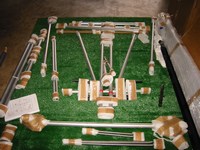
OK I've looked over the manual about three times all the way through, I think I am ready to begin working on the cabin today. I am going to try to complete the top,bottom,front, and rear portions of the cabin and if I get to it the seats and control stick.
WOW, this kit is really easy to assemble, I rarely had to look back at the manual because I had memorized how the different parts looked. When I did use the manual it was to verify bolt directions. Most of the bolts are already in their proper positions, you just loosen the nuts put the part in place and replace the nuts, easy. I spent 3 and a half hours and was able to assemble (without tightening any bolts) the cabin frame plus seats and control stick. I didn't tighten any bolts so I will have to remove some parts to reach certain bolts, for example, the bolts that hold the wing trailing edge U-brackets.
|
|
8/05/05
Purchased the materials for the floor: 1/4 inch plywood 4x8 and blue carpet 6x8 for both the floor and dashboard. Also got some misc tools: 24t/in hacksaw blades, 3/16 and 1/4 drills, 1.5in hole saw, 2in foam tape, utility knife, 1/4in tubing, 4in cable ties, glue for the floor, loctite, aluminum sheet, rivets.
|
|
8/7/05
I watched the entire cabin construction section of the DVD about 2 hours worth of detailed material!
|
|
8/8/05 (30 minutes)
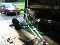
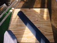
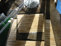
1) Cut out the floor from the plywood
2) Cut the seat tubes to allow the seats to rest on the main cabin tube AL9
|
|
8/9/05 (5 hours)
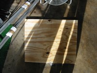
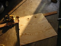
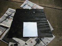
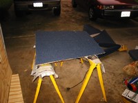
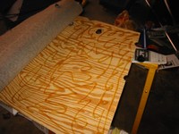
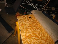
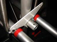
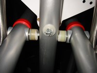
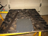
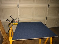
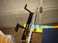
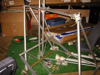
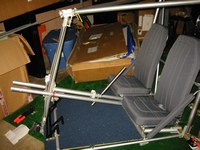
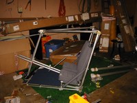

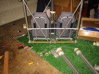
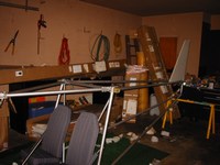
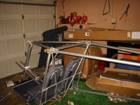
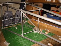
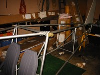
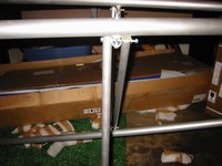
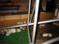
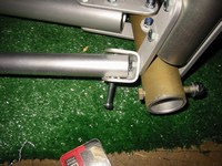
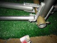
1) Constructed the floor glued the blue carpet onto the plywood I painted the back section to help minimize the tendency to absorb water and I attached an aluminum sheet to the underside of the floor, this is where the antenna will mount, the aluminum will act and the ground plate.
2) Began tightening the bolts for the cabin applying loctite to all bolts except the bolts on the seats.
3) Upon fitting the completed floor and pedals, I found that the rudder pedals would not bolt up apparently due to a change of position of the lower cabin triangle tubes realigning during tightening, also the bolts are too short to reach through the floor and tubes and nuts, I'll buy longer bolts tomorrow.
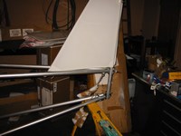
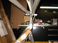
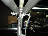
4) I began constructing the tail section, using a saw horse to elevate the lower tubes then attaching the vertical stabilizer, then the top tubes. I went ahead and applied loctite and tightened the top tube bolts to the vertical stabilizer top bracket because I couldn't see a way to reach the nuts later in the process.
5) Lastly, I loosely attached the center tail brace
|
|
8/13/05
I made a trip to Houston to pick up the 582 mount. When I ordered the kit I specified the 582 mount but I received the 912 mount. GreenLandings shipped the 582 mount to the Houston dealer free of charge, the only asked that I return the 912 mount.
|
|
8/16/05 (1.5 hours)
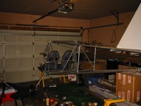
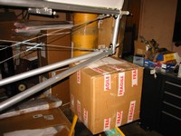
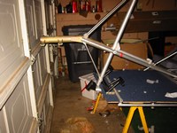
I installed the 582 mount. It is a very tight fit, I had to jump up and down on the mount to get the lower engine triangulation braces to fit.
|
|
8/20/05 (2 hours)
I tightened the rear fuselage including the vertical stabilizer tube, center tail brace, and the attachments to the forward fuselage.
Also I tightened up the wheels and inflated them with a bicycle pump to the point where they took shape but would still be difficult to roll, I don't want the plane rolling around unexpectedly on me just yet.
|
|
8/21/05 (2 hours)
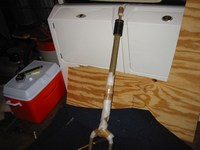
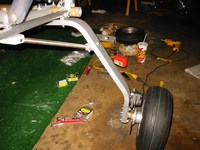
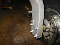
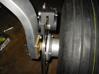
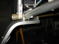
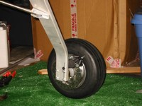
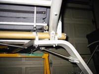
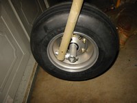
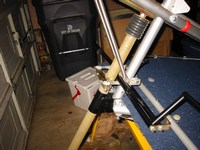
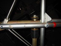
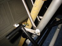
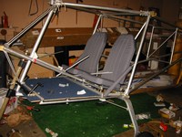
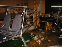
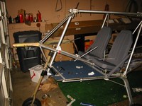
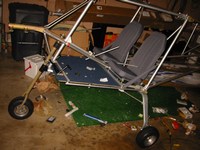
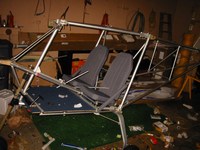
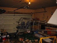
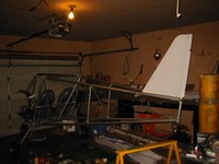
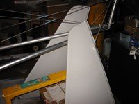
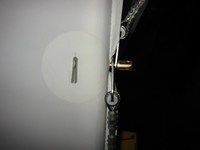
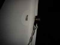
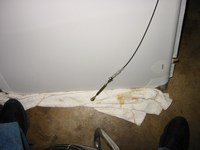
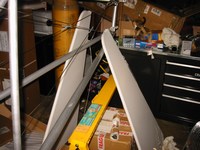
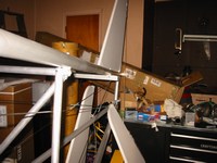
I had to take the main landing gear struts over to a friends house to drill the holes for the brake calipers. He had a very old drill press (weighed a ton) but it made quick work of drilling through the aluminum.
Later that night I attached the main landing gear and nose wheel.
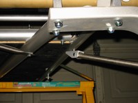
I also attached the horizontal stabilizer cables. These are difficult because you have to unbolt the rudder and elevator attachment bolts; however the nuts are on the inside of the fabric, and if they fall, they would have to be fished out. This would be possible on the horizontal pieces but impossible on the vertical piece. I used a closed-end wrench with tape on it to keep the nut and washer in place while I place the tangs on the bolts and then replace the bolts while not moving the nut and washer at all.
|
|
8/22/05
I attempted to contact the supplier of the rotax 2-cycle I purchased but I am having a hard time contacting him and getting the different components (gearbox, prop, exhaust). Right now all I have is the engine core and carbs. Also I'm strarting to have second thoughts on using a 2-stroke vs. a 4-stroke. All I hear from experienced users is the tendency for 2-strokes to quit. I want to take my family and friends up in the plane and I really don't want to rely on an engine with this reputation. I am now looking into 4-strokes. I looked into VW conversions, Subaru conversions, HKS, and of course the Rotax 912. On barnstormers.com I located a 912 (80hp) with 400hours on it, and it is here in Dallas. I called the owner and scheduled a time to come and see the engine.
|
|
8/23/05 (1 hour)
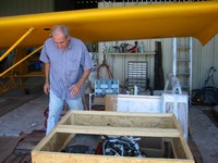
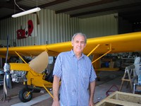
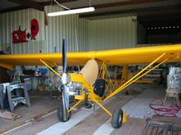
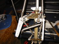
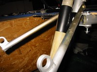
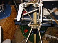
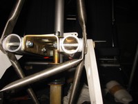
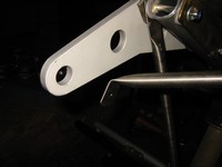
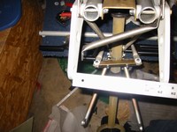
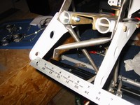
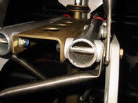
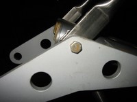
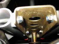
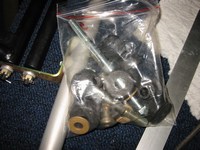
I went to Lake Dallas to view the engine and met the really nice owner, he had a SeaRey at one point and had an accident. The engine had since been run on a testbed and it looked great and ready to go. So I purchased it from him and took it home that day. Later that night I replaced the 582 mount with the 912 mount. I'll ship the 582 mount back to GreenLandings.
|
|
8/27/05 (3 hours)
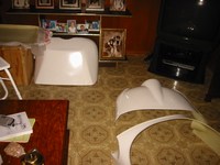
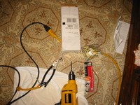
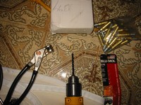
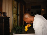

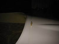
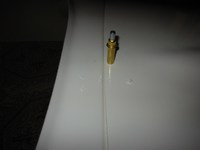
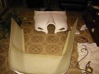
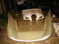
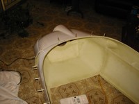
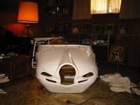
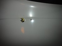
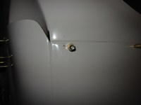
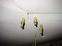
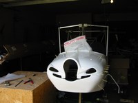
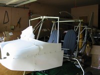
I assembled the cowling. The cowling does fit together nicely but is does take a good amount of effort to get everything to line up just right; I made a couple of mistakes and ended up redrilling 2 of the holes. I used 3/16" clecos to temporarily assemble the cowl.
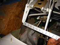
I found the mounting specs for the 912 in the installation manual, it says that the mount points are 5.60" apart however on measuring the 912 mount I found that the distance between the 2 "mount triangles" is about 7". Even with the barry mounts (1/2" each) this is too wide; I've decided to remove the aluminum saddle washers and use the nylon ones to bring in the triangles. This will also allow the 3" bolts to protrude through the nuts, otherwise they are too short when the aluminum saddle washers are used even if the outside washers are removed.
|
|
9/3/05 (4 hours)
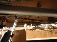
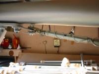
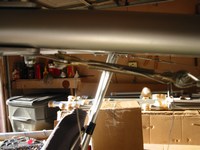
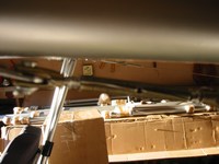
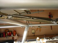
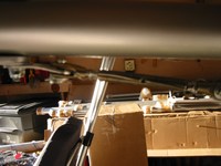
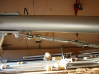
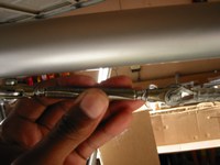
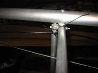
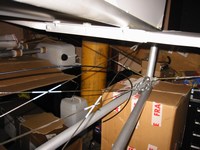
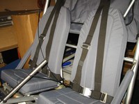
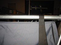
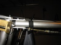
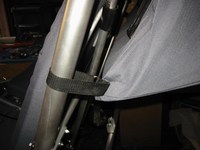
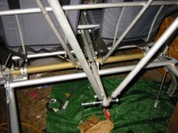
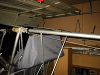
I finally tensioned the bracing wires in the rear fuselage. I originally safety wired the fuselage bracing turnbuckles using the double-wrap spiral method that I found on the web. After looking at some construction manuals I decided to undo the spiral wraps and rewrap the turnbuckles using the double-wrap without spiralling. This seems to be the more popular technique. I am using 0.032 sized safety wire instead of the "recommended" 0.040 and therefore want to make sure I double wrap all turnbuckles.
If I were to use 0.040 (actually 0.041) safety wire I could probably just single wrap them. I also ran the single trimmer bowden cable (apparently my kit did not include the UKMOD double cable trimmer setup). I looped the seat restraints over the top rear cabin tube over which the covering will attach. I attached the cargo bag to the top rear fuselage and the cabin uprights (I was told this would be nearly impossible to do if I installed the covering first). You can see my first attempt at building a flap handle,
the holes are not exactly in line so I will have to redo it (my kit was missing the flap handle setup).
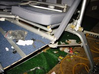
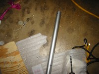
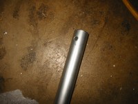
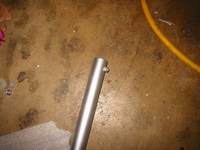
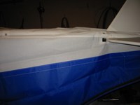
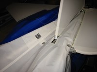
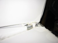
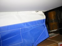
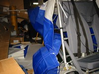
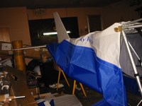
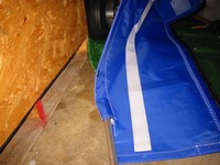
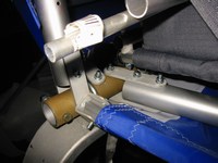
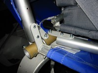
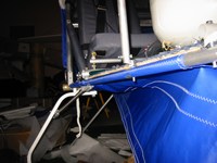
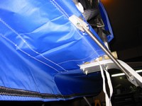
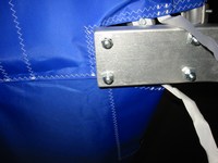
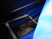

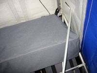
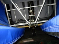
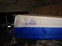
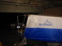
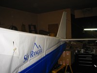
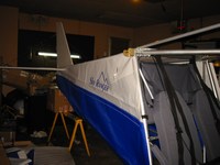
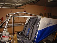
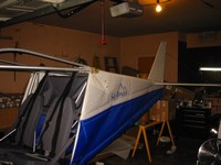
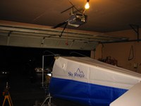
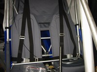
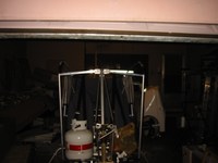
I am ready to put the covering in place (I won't fasten it until I run the control cables and get an inspector to see the aircraft in this state). First I removed the lower cabin side tubes and opened up the holes that attach to the U-brackets on the main tube (tu9). These holes have to be large enough to accept a small aluminum sleeve that keeps the brackets from collapsing inward. Also these tubes must be slid into their pockets in the front part of the covering. I covered my hands with baby powder to prevent oils from getting onto the covering.
|
|
9/5/05 (3 hours)
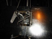
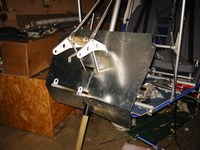
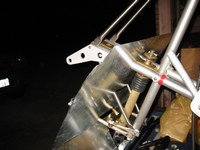
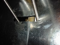
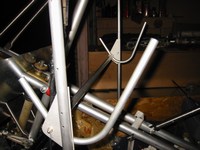
I replaced the aluminum supplied with the kit with 26 gauge galvanized steel for the firewall. My father owns an HVAC business and has access to this material, I was able to get a 3'x3' piece for about $12. The EAA members I have spoken to look down on aluminum as firewall material because of it's very low melting point (compared to steel). However steel does weigh noticably more. Cutting the round slots was not fun, but it was not too difficult with the angled snips (it helps a lot if the snips are brand new i.e. sharp). While I was in the metal cutting mood, I cut the throttle tube down to size using a tubing cutter.
|
|
9/6/05 (3 hours)
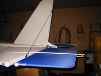
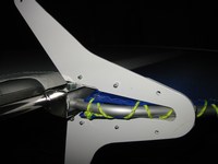
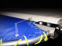
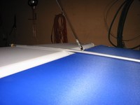
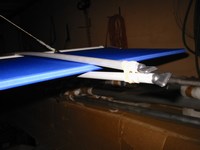
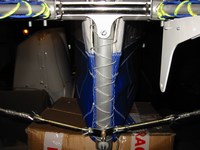
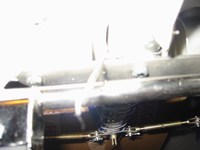
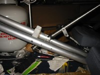
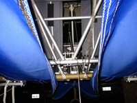
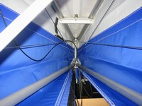
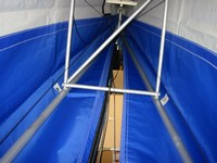
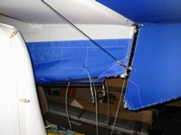
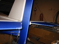
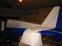
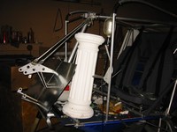
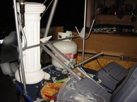
I wanted to start on the elevator and rudder so I went ahead and laced the back of the covering. I installed the elevator and supported it like they show in the manual, using two straight battens rubber-banded together. Then I drilled the connection piece and fitted the control horn. I also attempted to attach the rudder control horn but I'm not sure about the location of the rearmost set bolt, the manual shows the earlier rudder that did not have the ventral fin and thus was wider but shorter. I'll have to research to see where others are placing this rear bolt. I attached the nuts to the bolts holding the horizontal
stabilizers in place. Access to these nuts is horrible, I had to wrap the nuts with a single loop of safety wire and fish them in while turning the bolt in order to grab them out of the safety wire, very tedious process and I had to stretch the fabric at these openings as much as possible to get the nuts through. After I placed the rudder and elevator on, the plane is heavy in the rear again so I had to add weight up front (that is why the plaster roman column is up front).
|
|
9/11/05 (4 hours)
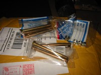
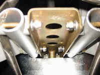
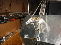
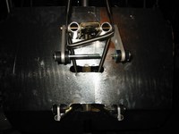
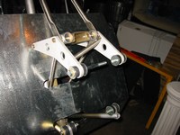
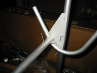
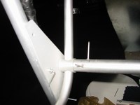
In talking with a technical counselor, I found out that the use of nuts with nylon inserts is a no-no in the engine compartment because of the heat. The heat can cause the nylon to melt and allow the nut to loosen, therefore, it is recommended to use all-metal lock nuts in the engine compartment. I ordered some all-metal nuts from aircraft spruce along with the correct length bolts. I also drilled the rivet holes for the throttle tube.
|
|
9/12/05 (4 hours)
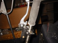
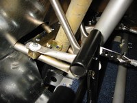
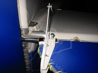
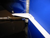
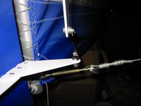
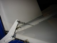
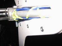
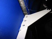
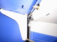
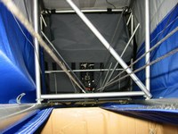
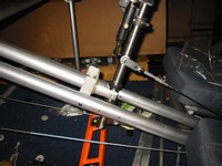
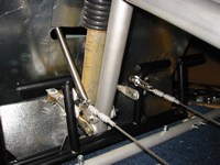
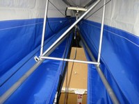
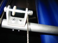
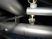
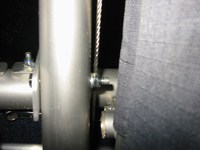
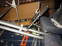
I completed the control horns for the elevator and rudder. Originally I tried sight fitting the brackets on the rudder for the control horn but I couldn't determine the correct angle to place them at, I had to look at finished SkyRangers online to see what angle other builders were using for this bracket. A slit in the rudder had to be cut with a soldering iron. I riveted the two control horns in place. I decided to attach the control cables. This was difficult as I kept having to rerout the cables because they would invaribly touch each other or one of the tubes or a bolt somewhere in the full range of travel of the control stick or rudder pedals.
|
|
9/13/05 (6 hours)
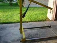
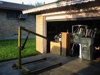
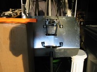
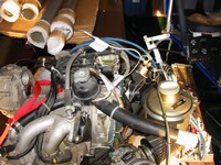
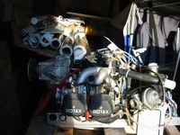
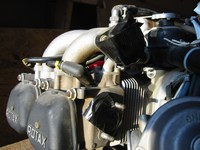
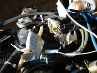
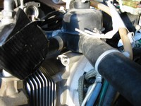
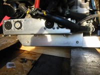
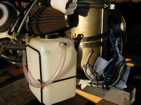
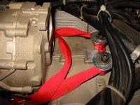
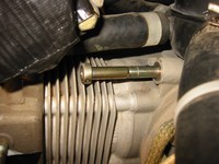
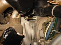
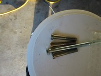
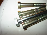
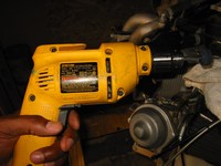
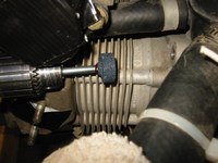
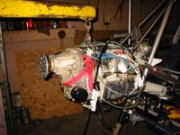
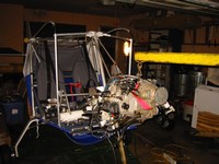
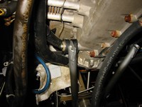
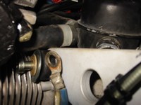
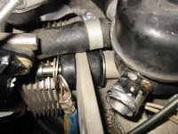
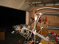
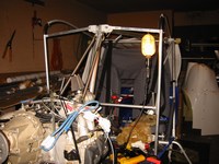
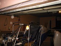
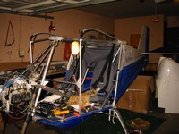
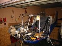
Over the weekend, I had a friend of my dad's drill the engine mounting bolts, I want to safety wire them after they are installed. My brother and one of his friends came over to help me attach the engine. I rented an engine crane to facilitate the process (it turned out to be a necessity). During installation I ended up removing the oil system and carbs and loosening the electronic module from its rear mount in order to be able to rotate it upward to avoid colliding with the upper passenger engine mount boomerang. I also ended up going to Autozone twice to get the appropriate allen wrenches to remove various metric screws. The engine cooling fins near the pilots side engine mount have to be ground down slightly to allow the bolt to align with the mounting hole.
|
|
9/19/05 (3 hours)
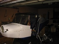
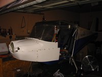
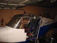
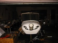

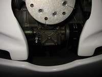
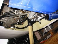
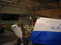
Over the weekend in Austin I went to the dealer near Houston to pick up the wheel pants and wing tips that came in, I also took the lexan with me, I wanted to use the pattern that the dealer has created to guide in cutting the windshield. Today I clamped the cut lexan and also clamped the cowling to the airframe just so get an idea of how it all fits together. Looks great! (In studying the windshield discussions on the forum I purchased some 0.080 (2mm) lexan which is considerable stronger than the supplied 0.060 (1.5mm) lexan. There has been talk of the stock windshield flexing at high speed and also some reports of stress cracking. The forum shows a 2-piece windshield that is considerably stronger and easier to replace in the event of a crack. In these photos I have the stock windshield, I'll create the 2-piece windshield later.)
|
|
9/25/05 (3 hours)
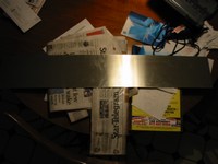
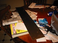
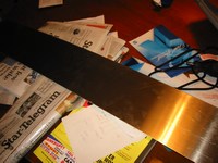
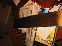
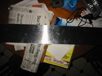
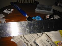
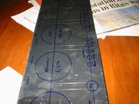
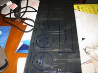
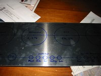
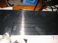
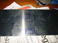
I decided not to use the fiberglass panel supplied with the kit in lieu of Aluminum that I purchased from a local metal shop. I began drawing the positions of the instruments and making measurements for the different cutouts. I wanted the Vertical Compass in the middle because this is one of the most important instruments in my opinion.
|
|
10/5/05 (4 hours)
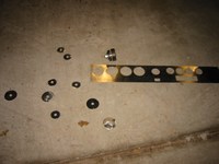
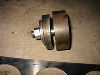
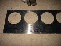
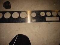

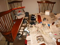
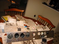
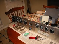
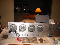
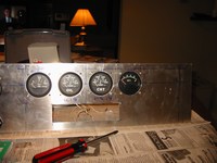
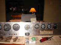
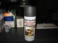
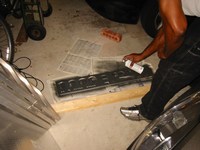
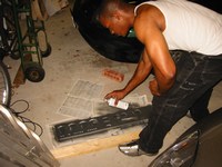
I borrowed a hole die punch that is designed just for aircraft instrument panels, one side cuts 2 1/4 inch holes the other side cuts 3 1/8 inch holes. I made the cutouts for the Altimeter and VSI with a dremel and a large (at least large for a dremel tool) milling head designed for wood,plastic, and soft metals. I drew the cutout on the metal and then just cut them out by hand with the dremel. The switch and circuit breaker holes are 15/32 inch and I copied the spacing from another instrument panel section that Pete gave me. The square holes for the hour meter and transponder were cut out with a cutoff wheel on a dremel. I riveted some aluminum angle across the top and bottom for rigidity. I acquired some textured paint from Home Depot and covered the panel with about 3 coats. I left the panel to dry overnight. The next day I attempted to fit everything onto the panel anly to find that the switches that I purchased are too wide for the holes. I ordered thinner switches and I'll return the "fat" ones. The circuit breakers fit perfectly.
|
|
10/12/05 (4 hours)
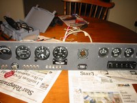
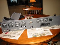
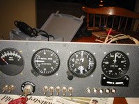
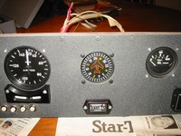
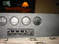
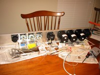
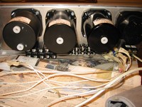
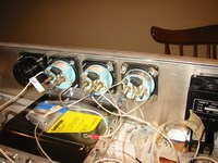
I finished the instrument panel and installed the instruments. I also began wiring the electrical components with 18 and 16 gauge wire. I still need to make a bus bar and attach it to the circuit breakers. The instrument panel looks good, however, I found that I was a bit too reserved in positioning the leftmost instrument hole and therefore there is not much space between the edge of the instrument (Airspeed Indicator) and the end of the panel. I'm not sure if there is enough exposed metal to actually fasten the panel to the frame at this point. I may have to attach aluminum extensions at each side (for a balanced look) in order to properly mount the panel.
|
|
10/19/05 (3 hours)
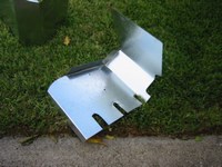
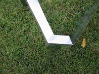
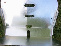
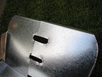
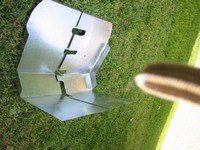
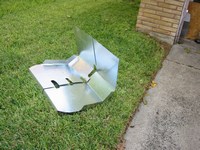
I've been thinking about how to attach the firewall to the sided of the cowling. Some recommendations have included, building fiberglass angles like the manual shows, using HVAC aluminized tape, attaching metal brachets. I finally decided to rebuild the firewall and use 'bends' to increase the stiffness. Eventually I will attach the sides of the firewall to the cowling by elongating one of the cowling bolts on each side. After rebuilding the firewall I found that these bends make the firewall sufficiently rigid that I may not even have to attach it to the cowling at all.
|
|
10/22/05 (8 hours)
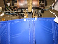
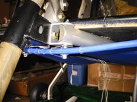
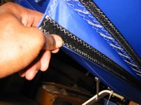
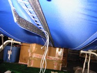
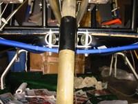
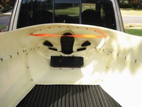
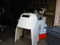
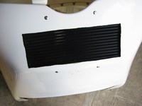
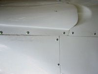
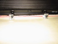
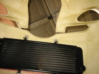
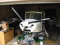
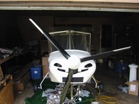
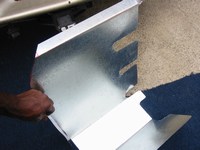
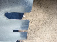
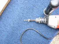
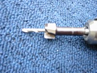
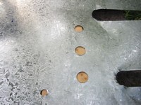
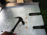
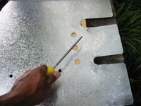
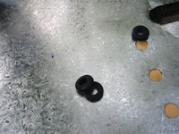
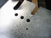
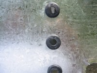
Busy day! I wanted to get the firewall installed today, and fit the cowling if possible since the spinner had arrived just recently. I purchased a 9 inch UHS Spinner cutout for an IVO Patriot propellor. I requested the metal backing plate per IVO's suggestion. First I needed to go ahead and pull the fabric up to the front of the floor. This was a major headache, the fit is very very very tight and I ended up making new holes in the fabric where the two protruding bolts hold the cross batten. I found that it was easier (slightly) if I went ahead and laced up a small portion (about 1.5 feet) of the front section of fabric. I removed the temporary cleco fittings from the cowling and cut out a section for the radiator to mount into. I then installed the screw fittings, the cowling is a lot more rigid now. I drilled some holes in the firewall for wires and hoses to pass through, I placed rubber grommets into these holes for protection. I ended up mounting and remounting the cowling and windshield about 5 times.
|
|
10/29/05 (6 hours)
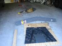
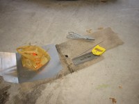
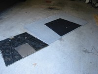
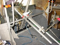
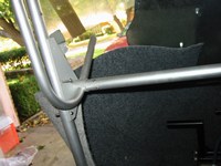
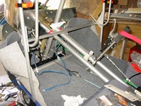
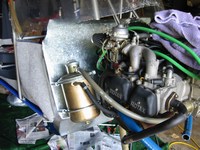
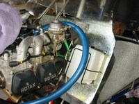
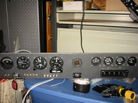
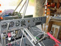
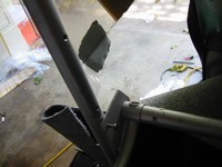
Another busy day! Since moving to Fort Worth into my mom and dad's house, I have not been able to work on the plane during the week, only the weekends. So I decided to start dedicating the bulk of the next few Saturdays to building. After seeing the pictures of the SkyRanger in the latest Kitplane, I decided that I wanted to redo the floor so that the carpeting goes up the lower cowling wall inside the cabin. I also attached the oil canister, regulator, and water overflow bottle to the firewall. I placed the instrument panel inside the cabin just to see how it all looks together. After attempting to fit it properly it seems like there is no other option but to install extensions on both sides of the panel. I've decided to attach the throttle cables to the passenger throttle stick, this allows me to cut the pilot's throttle stick and prevent it from impacting the rear of the instruments.
|
|
11/25/05 (12 hours)
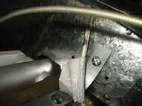
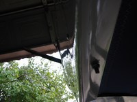
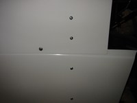
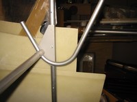
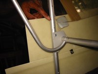
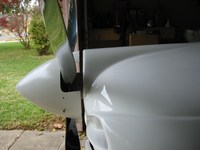
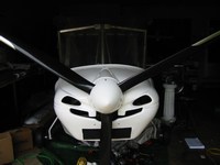
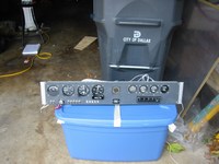
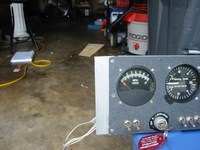
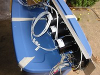
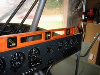
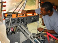
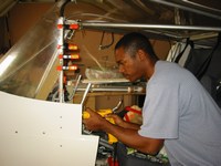
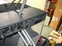
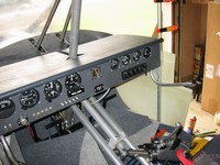
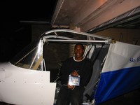
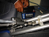
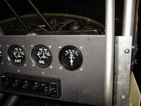
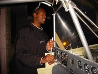
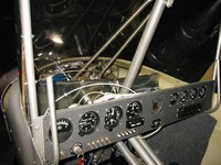
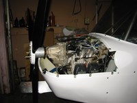
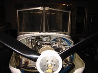
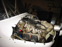
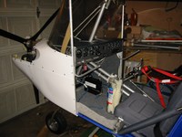
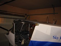
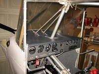

FULL DAY OF BUILDING! I devoted this full day to working on building the SkyRanger to the point that I could turn over the engine (not start it, just crank it). First I replaced my colorful (green rubber hose) tubing with actual fuel tubing. Then I attached the firewall to the engine mount with a piece of steel angle. Next I finally permanently attached the cowling. Next I leveled and installed the instrument panel, AND connected the wiring (this took longer than expected, but all electrical connections are complete now). Lastly, with the help of a friend, I attached the windshield. Everything looks great. With the propeller bolted on I connected the battery, checked the volt meter and hour meter, then turned the key and watched as the engine rapidly turned over for a few revolutions! Later that night I tried building the throttle mechanism but am not to happy about it, I want to make it more sturdy. The 912 I acquired has the carbs set in such a way that the throttle cables have to be pulled to increase engine rpm (the springs hold the throttles in the idle position), this is in contrast to the normal setup of the 912 in which the springs hold the throttle to the wide open position and thus the throttle has to pull the cables in order to idle the engine.
|
|
11/28/05 (1 hour)
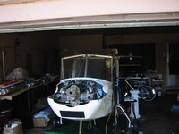
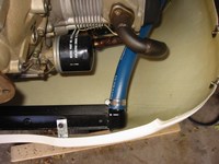
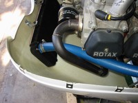
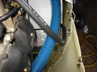
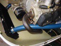
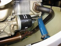
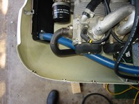
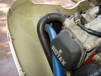
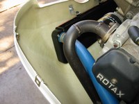
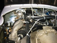
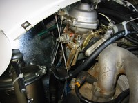
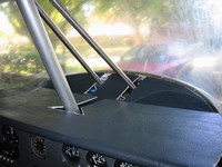
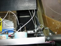
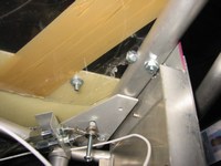
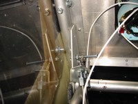
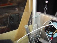
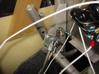
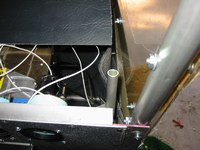
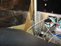
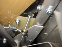
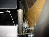
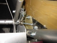
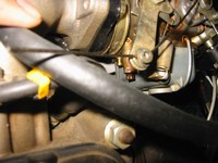
There are a few problems that I need to address. 1) The radiator hose on the pilot side of the engine touches the exhaust piping, I want to use a metal tube in this area and bend it outside the exhaust piping. 2) The primer nipples on the carbs are exposed and can allow air to enter the carb behind the throttle plate, fortunately these nipples are internally threaded, unfortunately the threads are M3.5 at 5mm not a very popular size, fortunately I found some M3.5x5 bolts at McMaster-Carr (www.mcmaster.com). 3) The throttle need to be more rigid, I think I'll try attaching the aluminum angle to the outside of the throttle tube and see how that works, hopefully it will not rub against the cowling and windshield, however this area is pretty tight. 4) Need to attach the carpeting to the cowling, I will use Velcro and attach the loop tape to the cowling and the hook tape to the carpet with epoxy. 5) I need to fit and complete the dashboard, I want to carpet the dashboard afterwards to cover the holes and have uniformity within the cabin.
|
|
12/6/05 (2 hours)
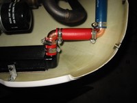
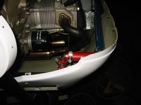
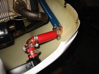
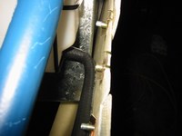
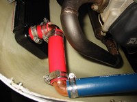
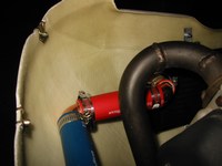
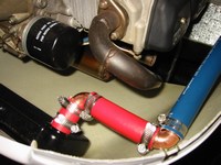
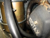
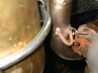
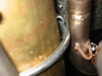
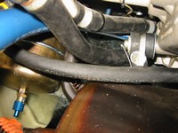
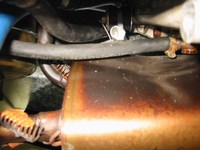
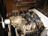
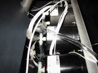
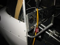
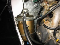
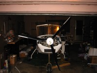
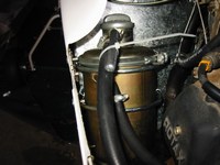
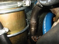
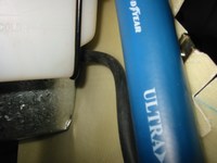
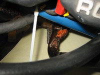
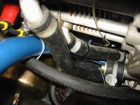
Today I wanted to remedy the hose rounting problems. I rerouted the pilot-side coolant hose so that it doesn't contact the exhaust pipe anymore. I used 2 copper 90 degree elbows and some leftover rubber hose that I had. I also checked the hoses near the muffler to verify that they would not contact it under engine operation, I may have to adjust the oil return line that is currently positioned right above the muffler. I lastly, added the tubing for the instruments.
|
|
12/8/05 (2 hours)
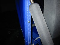
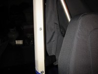
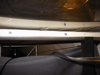
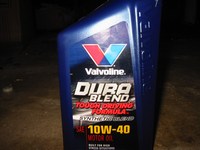
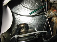
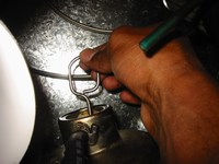
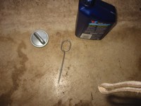
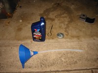
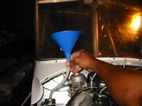
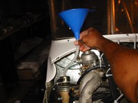
Today I attached the fabric to the rear cabin tubes, I had to use a soldering iron to burn larger holes through the fabric to fit the #8 machine screws I chose to use. The fabric that attaches to the top cabin tube had holes in the wrong places so I had to burn completely new holes in this section. Later I filled both the radiator and oil systems. I used the DexCool radiator fluid and Valvoline Heavy Duty Semi-Synthetic 10w40 oil recommended in the rotax bulletin for the 912.
|
|
12/11/05 (2 hours)
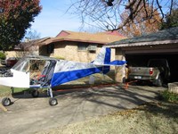
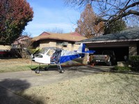
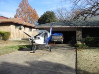
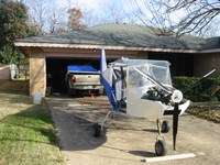
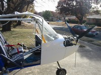
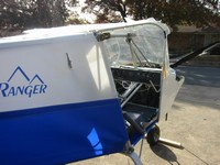
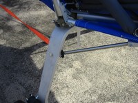
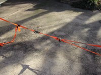
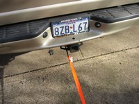
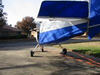
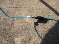
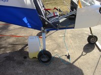
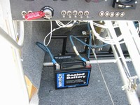
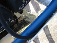
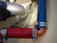
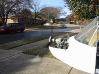
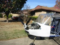
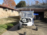
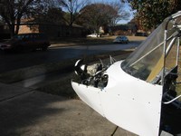
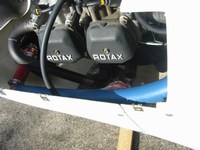
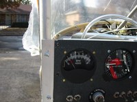
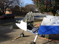
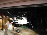
IGNITION!! Ok today was a beautiful Texas winter day. The high was about 67 degrees and it was nice and sunny. I wanted to take this opportunity to attempt to start the engine and verify the oil, fuel, and coolant systems worked properly. I previously topped off the oil and coolant systems, I also filled one of the fuel tanks with 4 gallons of fuel for a leak test. The fuel system I have includes a filter and a hand squeeze pump that can be used to fill the carb. bowls prior to ignition. I pulled out the plane and fastened it by the legs to my truck with straps. I set the fuel tank beside the aircraft and lowered the end of the fuel line into it. I then primed the system with the squeeze pump until the carb bowls were full and stopped accepting fuel. After I attached the battery, I pulled the choke, set the throttle to idle, turned on the master switch then the panel switch and verified the voltage reading, checked the area to make sure everyone was at a safe distance away, then turned the key to 'start'! The prop turned over rapidly about 5 times then the engine roughly fired to life pulling the plane about 2 inches forward. The engine seemed to run a little rough until I gave it some gas. Oil pressure stayed at 50psi, and the tach read 1000 which I know is really low. Playing with the throttle I revved the engine up to what the tach showed as 2000 but seemed a lot higher by ear. I had the thought that the tach (which I originally bought for a 2 cycle ducati ignition rotax) wasn't designed for the 912 (later I would find this to be true, so I need a new tach). I shut off the engine after about 1 minute and checked for smells, smoke, etc.. There appeared to be smoke originating from the muffler where I spilled some radiator fluid ealier, but that was the only issue I found in the engine compartment. I fired the engine back up to clear fuel out the carbs for final shutdown, the engine ran a long time just burning the fuel in the line (the 912 is a very efficient engine), I noticed that the CHT started to rise into the normal operating range, the oil pressure was always around 50psi, but the oil temperature gauge never moved from zero (I'll have to check the wiring). The engine finally started running rough again as the carb bowls emptied of fuel (apparently one before the other) and I finally just shut it down by turning off the key.
|
|
12/17/05 (1 hour)
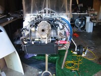
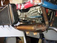
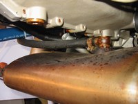
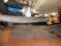
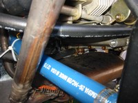
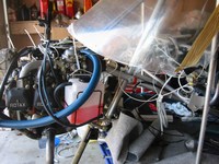
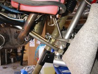
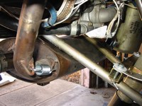
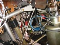
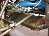
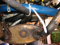
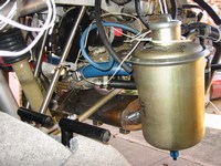
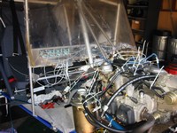
I scrutinized the current exhaust system today and decided that the muffler is just too close to the engine mount members. When the muffler heats up it is liable to vibrate against these mounts. Besides, the whole assembly is ulgy, so I need to design a new exhaust system, but I don't want to pay over 700 dollars for the standard rotax system.
|
|
12/23/05 (8 hours)
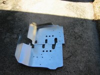
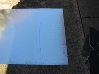
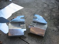
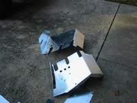
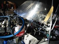
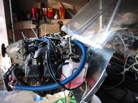
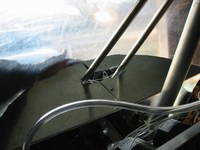
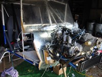
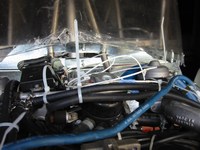
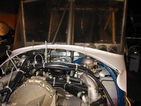
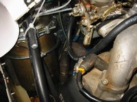
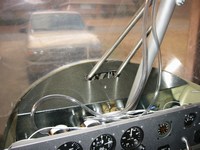
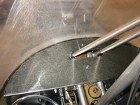
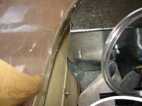
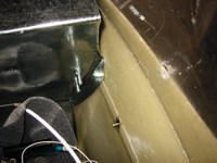
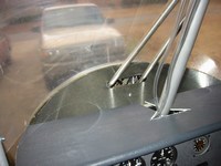
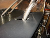
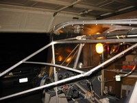
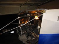
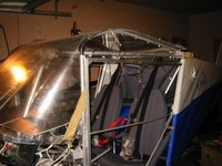
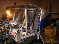
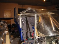
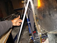
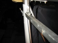
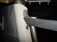
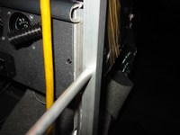
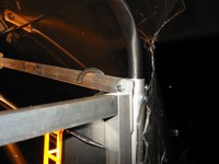
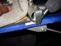
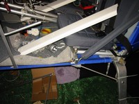
Ok Ok I know what you are thinking, "He's rebuilding the firewall again!". Yes, so I decided to rebuild the firewall and make it go forward into the windshield at the very top rather than adding another piece on top of the current firewall. It took almost all day but in the end, it looks great! I even had enough time to build the door frames and make brackets for the side panels that will go on later. I did what a lot of builders do and used 3/4 inch square tubing for the door front and top members (instead of the 1/2 inch round tubing supplied with the kit). The door frames are very light but strong.
|
|
12/24/05 (5 hours)
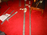
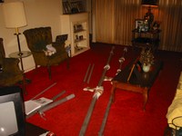
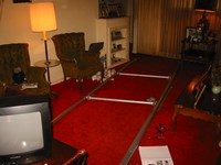
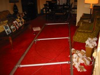
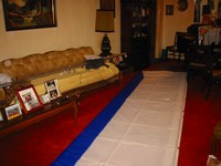
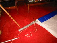
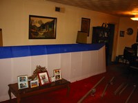
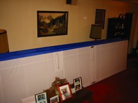
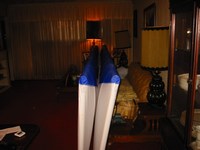
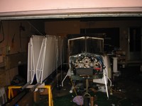
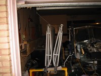
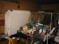
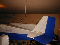
Ok Christmas Eve, I've already done all the shopping I need to do, so what am I going to do today? I know, I'll build the wings really quick. I was amazed at how fast I was able to build the wings. I used my grandmothers living room since it was carpeted. Warning! The wings take a lot of space to build, I found myself jumping back and forth over the wings to work on either side. It took about 3 hours for the first wing and 2 hours for the second. The hardest part was pulling the covers tight, this would have been easier if I had some assistence. The plans say to rivet the grommet that is used to pull the covers in place but I am going to leave the rivets out for now until I can do a final tensioning of the wings with some assistence.
|
|
12/25/05 (3 hours)
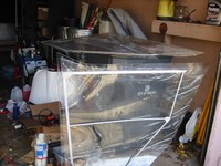
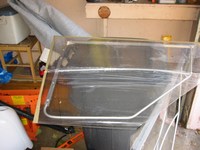
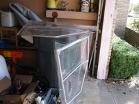
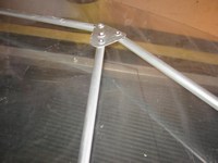
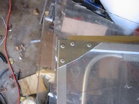
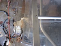
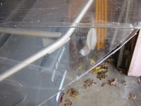
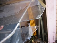
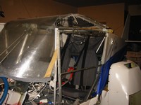
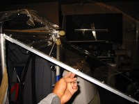
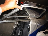
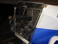
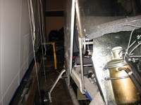
Ok Christmas Day night, after I spent most of the day with my family, I went over to my grandmother's to spend some time with her for Christmas. Inevitably I began working on the plane later and decided to see if I could put the lexan on the door frames. Fro these I simply held the lexan in place and drew an outline of the planned cutout. Cutting this much lexan in such a short amount of time really taxes the hands and I found mine pretty useless afterward. I did manage to get the lexan riveted. I tried to a single piece of lexan for each door but was unable to get it to flex enough in the middle to properly fit the middle beam of the door (the middle beam of the door curves out considerably at the shoulder area for better airflow and shoulder room). I ended up cutting the lexan at this beam and riveting the two pieces together here. The dealer said I would have to do this but I wanted to see if I make a single piece work first.
|
|
12/26/05 (6 hours)
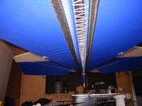
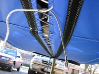
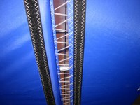
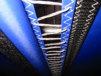
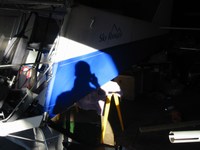
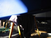
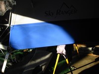
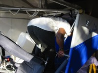
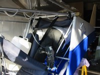
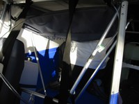
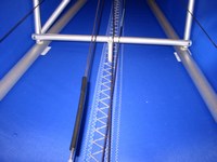
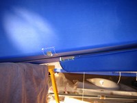
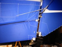
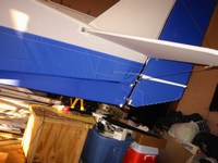
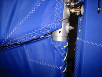
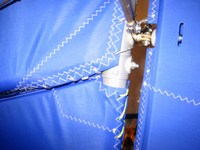
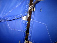
Here is the moment I've been dreading for a long time. LACING THE FUSELAGE! I devoted the entire day to this task, basically, the fuselage skin is laced with a string from nose to tail, like a shoe lace only 12 feet long (not fun). I cut the thread into 3 pieces so it would be easier to pull through the holes without pilling the entire 20 feet or so through each hole. This definitely took a while and was hard on the hands. I used 2 small needle nosed pliers to facilitate the task. After I laced the complete length of fuselage, I went back over the entire length 3 times pulling the thread tighter and tighter each time until the gap between the two sides averaged a little over 1/2 inch. Afterward I installed the ventral fin. This was an even bigger pain as I had to put a sawhorse near the rear of the fuselage and crawl into the fuselage, balancing myself on the lower side tubes and making sure not to step on the fabric (or else I would probaly punch right through it). I had my grandmother take pictures of me in the rear fuselage (really not fun).
|
|
1/14/06 (3 hours)
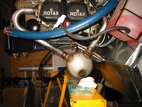
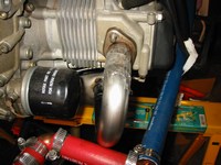
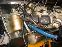
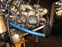

Over the early part of January I was able to locate a Rotax muffler for the 912 on barnstormers.com for $175 with shipping, unfortunately the tubes supplied were only suitable for the exhaust out of the muffler (1.5 inch). I decided that I could purchase 1.25 inch stainless steel tube and get it mandrel bent at a muffler shop. I searched for a place that would bend stainless but the minimum diameter that they all were equiped for seemed to be 1.5 inches. Finally, I found some prebent stainless on burnsstainless.com and decided to purchase 4 of the stainless U-bends from them. I could cut these to the proper angles and weld the ball joints and sockets from the current exhaust system. These U-bends are not cheap at $25 each. The header connections on the muffler are 90 degrees apart, which made the calculation of the proper angles for the headers easy (if one of the angles of a triangle is 90 then the other two combined must add up to 90 also). So if I set the muffler under the engine with header connections in a perfect 'V' then the angles on both front and rear headers will be 45 degrees. After visually positioning the muffler I measured that the muffler would be tilted toward the front by 10 degrees around its axis thus making the rear header angle 55 degrees (45 degrees + 10 degrees) and the front header angles 35 degrees (45 degrees - 10 degrees). I cut the U-bends at these angles and also cut the ball joints and sockets off the current muffler system. Later I taped the header pieces together and tested the fit. The system seems to fit great! However, new issues arose. I will need to re-route both the oil hoses and the radiator hoses to avoid touching the new header tubes. On a better note the new rear header would not even come close to the oil canister! So now all I have to do is cross my fingers and get these tubes welded and hope the post-weld dimensions are not too different. I know a guy that is a great welder but he lives over an hour away.
|
|
1/28/06 (3 hours)
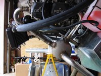
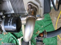
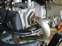
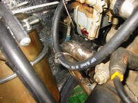
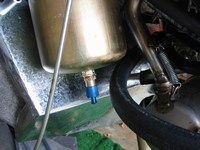
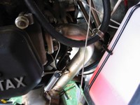
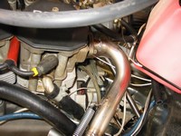
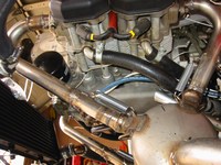

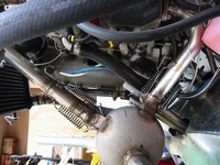
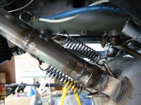
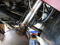
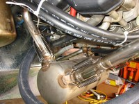
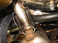
This weekend I went out to Farmersville to get the muffler and pipes all welded up. The system fit like a glove, so I fastened all the pipes to the engine and attached the muffler to the pipes with Rotax exhaust springs. The accepted safety practice is to safety wire the springs; in case of breakage due to vibration, the spring does not fly away and cause damage to cowling, firewall ...
|
|
1/31/06 (1 hour)
I was able to have a EAA Technical Counselor come by and take a look at the plane. He was very knowledgeable and offered me a lot of advice to get the plane airworthy:
1) Chaulk the firewall holes where cables and wires run through
2) Close up the large firewall holes that support tubes run through (the idea is to get the firewall as close to air tight as possible to prevent exhaust fumes from leaking into the cabin in case of an exhaust system malfunction. I'm not sure how possible this is given the firewall design and the support structure that runs through it.)
3) Safety wire the exhaust springs. (which has already been done)
4) Check interference of the control cables. (the bolt through the flap support bracket is very close to the rudder control cable, we don't want it to have the possibility of binding)
5) Have at least two threads of the bolts protruding from ALL nuts.
6) Bundle all electrical wires.
7) Tie wrap all vibration sensitive components (wires, hoses ...).
8) Placard all instruments, switches, breakers
|
|
2/4/06 (3 hours)
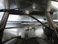
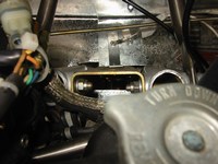
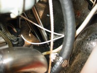
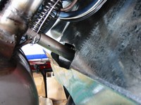
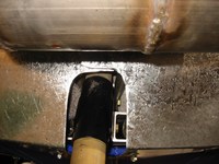
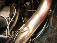
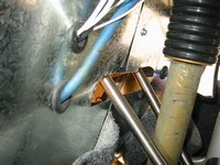
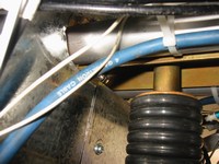
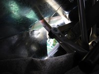
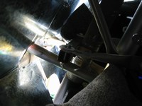
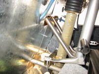
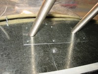
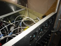
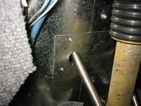
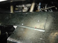
So I set out to make the firewall as air tight as possible. First I covered the oval shaped holes through which the engine support tubes run. However the actual engine mount hole is irregularly shaped and is very unlikely to be able to be completely sealed off, I'll have to get some advice on this part.
|
|
2/9/06 (2 hours)

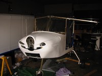
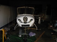
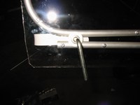
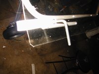
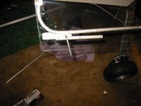
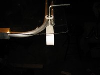
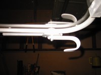
Tonight I wanted to get the door handle/locks working. I saw the design on the skyranger yahoo group and decided to imitate it. The end result works but I'll have to trim the composite side panels to allow the door to be closed easier.
|
|
2/12/06 (3 hours)
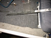
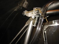
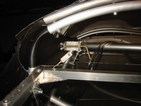
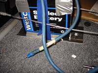
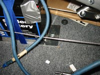
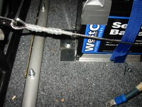
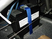
I decided to remove the temporary support struts that have been holding the front cabin uprights to the wing U-brackets. These are no longer needed now that the windshield is in place. I could not find a battery tray on the internet so I designed and built one from 1/2 inch aluminum angle and 3/16 aluminum plate. I riveted the angles to the plate and bolted the plate to the floor using holes that I had previously drilled up through the floor. I placed a nylon strap between the tray and the floor, this is used to strap down the battery so it doesn't fly around the cabin (very bad in turbulence).
|
|
2/19/06 (2 hours)
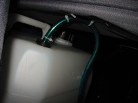
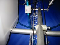
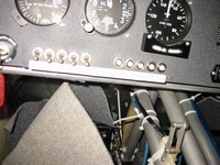
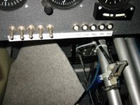
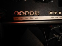
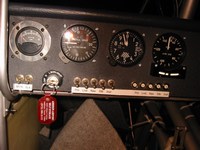
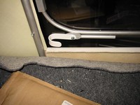
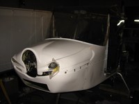
Tonight I ran a temporary fuel line made of copper. This line is far too soft so I will replace it with a stainless steel one later. I found that the cargo bag rests on the bend of the fuel line, I will have to remedy this when I get the steel line. I also labeled all the switches and circuit breakers.
|
|
2/24/06 (5 hours)
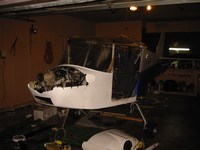
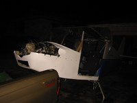
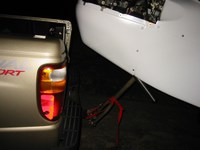
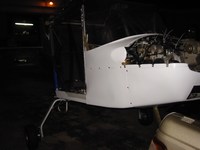
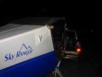
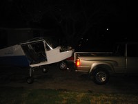
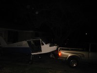
Tonight was a very special night! After weeks of trying to rent a trailer and trying to wait until the weather was just right (not too windy and not raining) I decided to just forget about the trailer and timing altogether. So tonight I began by making about 4 trips to the airport (about 4 miles from my grandmother's house) taking all my tools and workbenches. I also took the wheel pants, ailerons, flaps and all other littler things that I could get by myself. Later that night (11:00pm) my brother came over to help. We loaded the wings into my truck in a triangle shape (I placed the leading edges on the bed and tied the trailing edges together at the top) and he followed me in his car to the hangar. He followed closely so no one would rear end me and the wings due to the fact that the wings stuck out maybe 10ft from the back of the truck. Afterwards, back at my grandmothers house for the final trip, I removed my tailgate and tied the nose fork of the plane to my trailer hitch. I would tow the plane on it's own wheels to the airport VERY SLOWLY. With fully inflated wheels, I towed the plane with my brother following close behind with emergency blinkers on to ward off any traffic. Traffic was almost nonexistent, which was the plan. It was almost 1:00am when we finally arrived at the hangar with the plane. The scariest parts where going up hills and making sure the ventral fin at the rear of the plane did not contact the ground. We made a few detours during the last trip to avoid many of the small inclines. We successfully got to the hangar and I decided we might as well put on the wings while I have another person here to help me. My brother wasn't too enthused but he helped anyway. This was the first time I saw the plane with wings. Beautiful! (even though the flaps and ailerons are not on).
|
|
2/26/06 (4 hours)
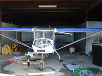
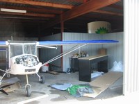
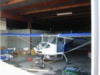
After throwing a surprise party for a friend I decided to come to the hangar and take some pictures of the plane. Before I knew it I was working on the flaps and ailerons. I completed riveting the aileron control horns and went ahead and attached both the flaps and ailerons to the wing. That went fast, so I decided to try to run the aileron cables. Looking at the manual I could see that there is one wire for each aileron that connects it to the control stick and a final wire that connects both the ailerons together. The first pulley I detached from the interior of the wing only to find that there is a ball bearing in the middle stradled by two washers. This is a great design and shows the thought and detail that went into the creation of this kit, unfortunately this also would be a big pain to put back together in such a small space. I managed to do so in about 30 minutes. One down three to go I thought. The next one I decided to try and just force the cable end through the bracket with the pulley still in place, this was difficult and required a lot of force and strong fingers. Success! This would cut the time considerably, I finished running the rest of the cables in about 30 minutes total. The ailerons now work! The flaps also work but since I do not have a flap detent lever (was not found in the kit), I'll have to make one soon. I finished up the work and decided to call it a day when some of the other hangar tenants came over and introduced themselves. I spent about another hour talking about my plane and getting to see theirs! Great bunch of people.
|
|
3/4/06 (8 hours)
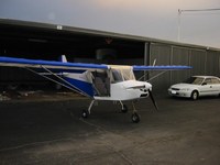
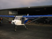
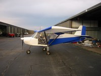
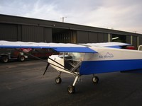

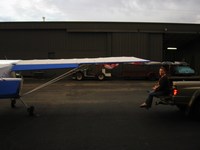
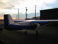
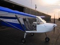
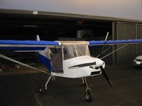
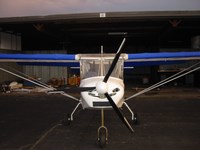
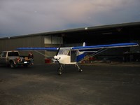
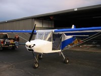
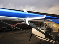
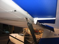
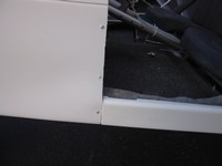
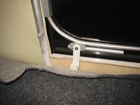
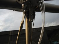
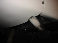
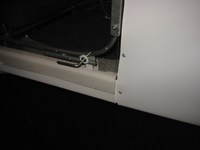
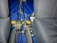
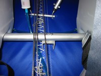
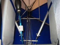
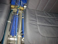
Today I reserved entirely for working on the plane and getting it to the point where I could start the engine. First item on the list was that front port-side wing bolt that I had not gotten to go all the way through when my brother help me put the wings on initially. My dad came over to see the plane an I got him to push on the wing while I hit the bolt with a rubber mallet. Success! Next on the list was trimming the cowling so the fiberglass side panels would fit up against the front cowling nicely. Armed with a dust mask and goggles, I trimmed away at the cowling with a dremel tool. After fitting, timming, fitting, trimming a number of times, I finally had a decent looking fit. I fastened up all the bolts that secure the cowling to the frame. I noticed that some bolts didn't have at lease two threads sticking out of the nut, I'll have to replace these with bolts that are a little longer (the aviation standard is to have at least 2 threads protruding out of the nut). Ok with the cowling on I decided to reverse the flap handle bracket in order to get it out of the way of the control cables, also I wanted to put the port-side pulley closer to the other set of pulleys (the pilot's seat is uncomfortably close to this pulley as it stands now). I successfully moved the pulley and the flap bracket, however, the bracked now positions the flap handle too low for operation. I attempted to bend the flap handle to a flattened 'S' shape but the tube cracked at the middle hole. I'll have to get thicker tubing that will withstand the amount of bending that needs to be done. Later, when one of my friends arrived, I added vent holes to the gas tanks. I also got her to help me refill the brake system. Initially I had filled the brake system months ago only to find that the majority of the fluid had leaked out somewhere. I first resealed all the connections and then proceeded to fill and bleed the system. The brakes are very, mushy and not strong at all, some have contributed this to the possibility that some of the kits got defective master cylinders, I'm beginning to think my kit is one of those.
|
|
3/5/06 (2 hours)
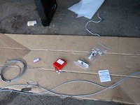

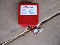
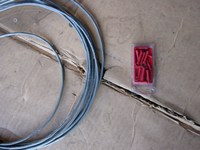
So I wanted to try to wire up the NAV/Strobe lights. I had purchased these cool LED NAV/Strobe combination lights. These lights have the red and green wingtip lights (green for starboard or right/passenger side and red for port or left/pilot side). Also they both have a white position light that shines out the rear and a strobe light in the center. Really cool design. After about an hour of attaching the pin connectors to the wires (the strobe driver and strobe lights have 3-pin connections), I ran the wire over each wing from tip to root and down to the strobe driver that I had placed under the pilot's seat. I connected the lights and strobe driver and decided to hook up the battery and see if it all works. First the good news, the stobes worked flawlessly and the NAV lights were bright. Now the bad news, I had positioned the light marked with a red label on the port side (pilot or left side) and I placed the light marked with a green label on the starbord side (passenger or right side), imagine my horror when I saw that both lights were "RED"! Hmm the FAA may have an issue with this, but more than that, I had ordered this light system almost a year ago. My only hope was to contact them and see if they would exchange my mislabeled light for an actual "GREEN" one.
|
|
3/11/06 (3 hours)
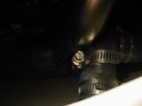
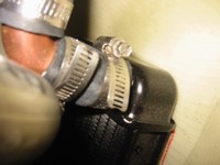
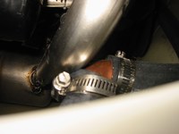
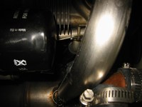
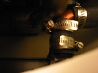
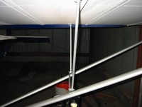
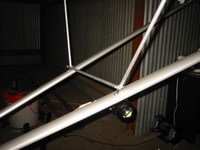
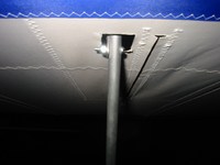
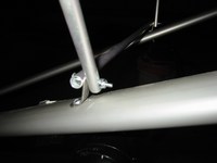
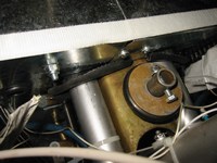
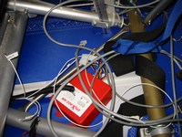
I was able to contact Aircraft Spruce and they worked with me to get me a GREEN NAV light from the manufacturer. The manufacturer (GS Air) actually contacted me and requested that I send the mislabeled light to them directly so they can send me a matching replacement. So while I am waiting on a replacement I decided to some unrelated work. I completed the 'Jury Struts' this evening. These help prevent the wing struts from buckling under compression, should the plane ever become inverted. These were simple just position the tubes, drill, and cut in place. I also noted that the pilot side front exhaust pipe touched the radiator outlet pipe, this will definitely have to be remedied. I had been wanting to put some type of seal or protector between the main engine mount tubes and the firewall. I cut a piece of oil hose and filled the small gap with it. I also noted that for the strobe driver, I will need to make some sort of tray to position it under the pilot seat.
|
|
3/14/06 (2 hours)

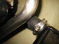
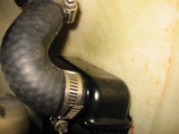

My first attempt at remedying the exhaust pipe collision is to use a water pump bypass hose that I acquired from O'Rielly Auto Parts. This works OK but when the top cowling is in placed, the hose and exhaust pipe are only about 1/4 inch apart, not enough for my comfort, I'll most likely get the pipe cut down a bit and re-welded.
|
|
3/18/06 (2 hours)
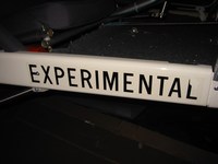
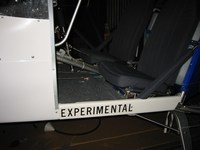
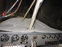
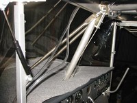
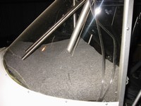
I had purchased the required 'EXPERIMENTAL' labels from LEAF (Leading Edge Air Foils) and decided to go ahead a put them on. These, by law, must be visible to anyone entering the craft, therefore, the best place to put these would be on the side panels, not aesthetically pleasing but will pass inspection. I cut some carpeting to get an initial fitting and just to see how good the cabin would look carpeted.
|
|
3/23/06 (3 hours)
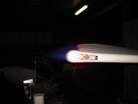
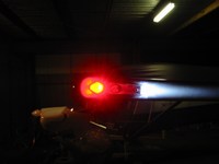
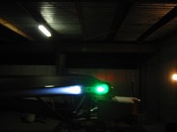
ALRIGHT!! The GREEN NAV light arrived and I couldn't wait until the weekend to put it on and try it out. LOOKS GREAT!!
|
|
4/3/06 (2 hours)
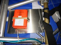
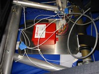
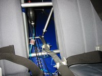
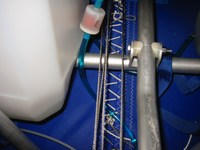
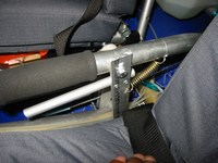
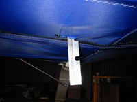
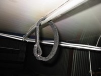
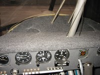

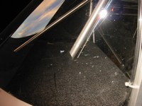

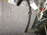
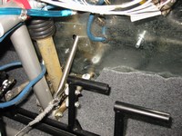
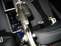
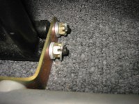
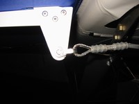
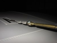
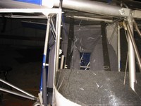
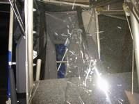
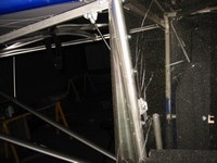
Today I had just a short time to work, so I began fitting metal trays under the seats to hold the ELT and Strobe driver. I also fitted some straps to the doors to make them easier to close. Up to this point, closing the doors from the inside has been challenging, usually I would reach out and grab the mid-door struct with my fingers and try to pull the door down. It worked ok for me due to my long arms, but others have been less successful. I took several pictures today of things that I have accomplished previously, including the oddly curved flap handle and flap detent bar that protrudes beneath the cabin; the final carpeting glued down on top of the dashboard and bolted in the lower cabin section; brake master cylinder epoxying; cotter pin closures. I found that the Wye fitting in the brake master cylinder would leak sometimes (I had previously managed to strip the threads inside the master cylinder). I decided that I would epoxy the fitting on. I took off the master cylinder and cleaned it up and realized that the threads were nylon. This is why the thing got stripped, I never expected nylon threads on a brake system, this design is a recipe for failure. I could see inside where the stainless steel Wye fitting had stripped the threads almost bare. Fortunately the threads run pretty deep and there were still some good threads further in, so I cut a small piece off the bottom of the master cylinder (further verifying that the threads are nylon). I mixed some 5 minute epoxy and threaded the Wye fitting into the master cylinder as far as it would go (hopefully the DOT 4 brake fluid won't attack the epoxy). The brakes work a lot better now and don't leak. The final pictures are of the windshield. In the course of fitting the dashboard, I managed to scratch the inside of the windshield numerous times, but never fear, I had ordered some NOVUS plastic cleaner/scratch remover and I should be able to restore this windshield back to scratch free condition soon!
|
|
4/6/06 (1 hour)
The EAA techincal counselor came over and did a second techinical inspection today. Here are some things he said I should work on:
1) Pretty up workmanship, basically slow down and make little things (like brackets) nicer looking, round off sharp edges, trim lexan to smooth edges...
2) Air-proof firewall, need to close up large side passages and seal smaller holes with RTV
3) Safety wire turnbuckles
|
|
4/15/06 (0 hours)
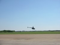
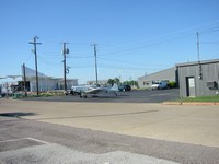
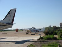
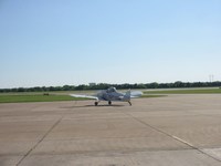
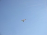
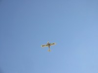
VIDEO
Some interesting things going on at the airport!
|
|
4/15/06 (6 hours)
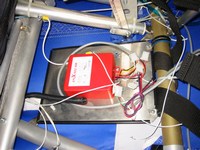
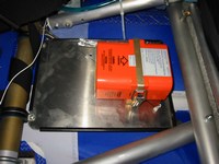
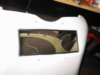
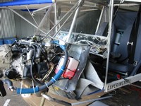
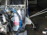
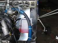
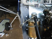
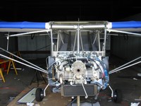
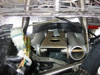
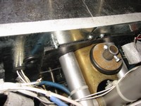
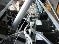
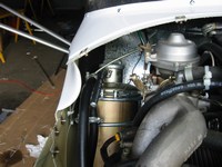
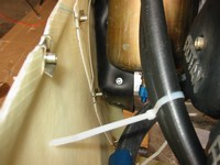
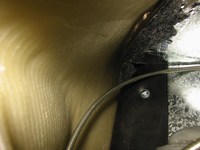
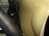
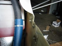
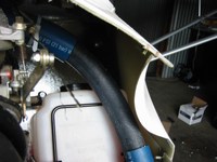

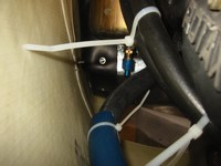
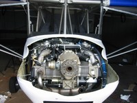
I got a lot done today. To start things off I put thin rubber strips around the edges of the underseat trays and radiator inlet, for asthetic and safety reasons. The major item of the day was to seal off the sides of the firewall. I did this by securing 4 inch rubber strips to the sides. These serve two purposes; first, it airproofs the sides of the firewall to keep out carbon monoxide, second, it protects the fiberglass from the sharp edges of the metal firewall. This job was a real pain because the entire cowling had to come off in order to do it properly. I took the opportunity to readjust the forward portion of the firewall; it now rests a little lower than it did initially (just under the front windshield-cowling intersection). I also trimmed off the sharp tabs that were on the underside of the front portion of the firewall, and I put aluminum tape around the edges to protect hands. The completed modifications look great!
|
|
4/16/06 (3 hours)
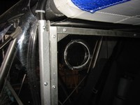

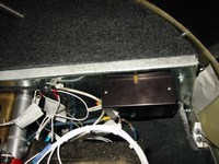
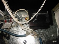
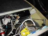
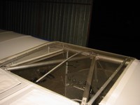
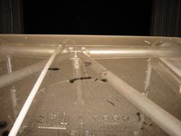
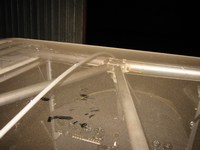
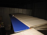
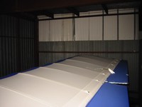
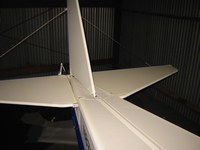
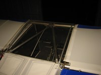
Today I cut out the circular holes for the window vents, I'll be needing these for the summer months. I also decided to go ahead and mount the encoder for the transponder. The only place I could find enough room to mount this was on the firewall right behind the transponder. I'll have to build the wire harness in the next few weeks to connect the two together. Lastly, I riveted the center batten into place. During some test runs of the engine I found that the roof would vibrate a lot and make a lot of noise, this batten should quite things down considerably. I also took some shots of the plane from above.
|
|
4/27/06 (3 hours)
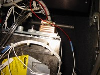
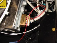
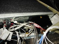
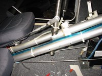
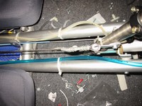
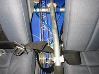

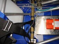
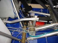
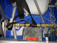
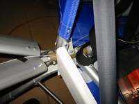
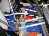
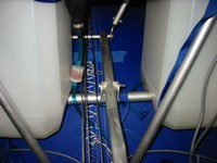
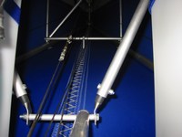
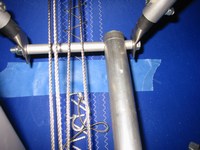
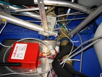
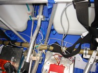
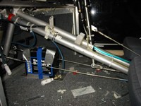
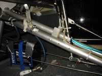
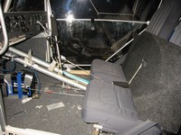
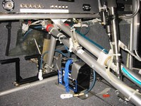
I met a guy named Paul that works in a hangar nearby that owns a transponder repair business. He offered to build the wire harness for me. This was a stroke of luck, because after looking at the parts included with the encoder I found that I would have to buy a special tool (4-Indent Crimping Tool) in order to crimp the "machined" D-Sub pins onto the wires. The cheap version of the tool cost about $30 the military spec version is many times more. Paul happened to have the millitary spec version!! So now my transponder is hooked up. I haven't tested it to see if it lights up just yet (that's the extent of my transponder testing capability). I took some pictures of the underseat area and the area behind the fuel tanks, I want to put the transponder and radio antenna here with a large groundplane to get a good range from my handheld radio. Also I have an idea for upgrading the brakes. More details to come...
|
|
5/06/06 (12 hours)
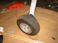
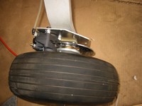
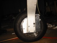
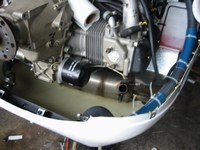
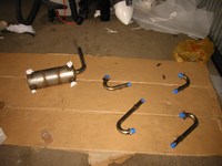
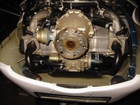
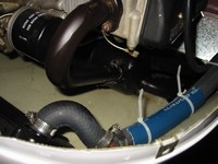
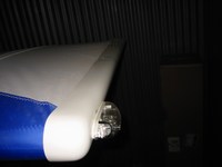
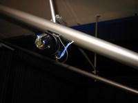
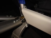
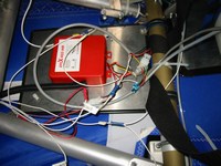
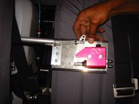
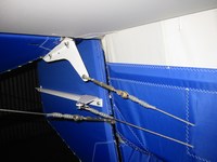
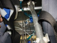
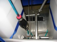
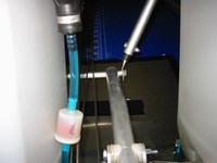
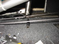
So I decided to do a weekend blitz on the SkyRanger. Today I got a lot of work done. First up was the brake system. The original brake system, or more specifically the master cylinder, has been unanimously voted as garbage on the yahoo group and I agree, it has to go. I manufactured some larger brackets for the calipers in order to provide more mounting surface for the wheel pants (or 'spats' as they are called in Europe) and I created a mounting plate for the 'Kart' master cylinder that I purchased from 'Comet Karts'. If any industry knows something about braking systems, it's the racing kart industry, and I'm not talking about the little 5hp sissy go-karts we are all used to, I'm talking about the 40hp 100mph true 'Karts'. There brake systems repeatedly stop the 'Karts' from 100mph all day long, surely they will work on an aircraft that lands a couple times a day! I haven't decided where I will mount the master cylinder just yet. The last component of the new brake system is the brake lever. This will be the weakest link, because I can't find one with the stroke that I really need to use the new master cylinder to its full potential, I may have to 'modify' one or the other. Anyway the brake lever is a simple mini-bike brake lever with a standard cable. The end of the cable will actuate the lever on the master cylinder. I need about 1 inch of travel, however the brake lever only offers 1/2 inch. Another part of the brake system that I am replacing is the brake lines. These are nylon tubes on the original system, I am replacing these with stainless steel braided lines, wow they look great too! Onward! I finally got the pilot front exhaust pipe re-welded to provide more clearance for the radiator hose. I had some exhaust high-temperature ceramic spray coating lying around so I decided to remove the rest of the exhaust system and 'paint' it. It looks really good in black! Later I re-fitted the exhaust system and re-safety wired the springs. This was a real pain to do with the cowling on, previously all exhaust work was done with all the cowling removed. The spray coating is dry to the touch but will actually 'cure' during the first run-up of the engine, when the exhaust temperature rises to normal levels. Next, I safety wired all the turnbuckles. I also riveted the data plate to one of the tubes near the tail section (I had to bend the data plate into a curve so if would fit nicely around the tube). I decided to use the original location of the VHF antenna as my transponder antenna location instead, so I removed the VHF antenna and installed the transponder antenna there. Next, I ran the transponder antenna cable under the floor. Next, I made a large groundplane and mount for the VHF antenna. This was simply a large piece of 0.063 inch aluminum sheet, onto which I bolted a 1 inch aluminum angle. This angle actallu supports the antenna as well as the BNC connector that will attach to the antenna wire that goes to the radio. I had fun soldiering the BNC connection to a wire that will attach to the antenna, I hadn't soldiered in a long time. I placed the completed antenna plate under the fuel tanks behind the seats. Next, I finally riveted the wing tips. Then I secured the wiring for the NAV/STROBE lights under the pilot seat, and tested the lights to make sure all wiring was ok. The lights worked great! Finally, I ran the landing light wires through the wing struts, I had previously had them taped along the trailing edge of the struts because I just couldn't successfully 'fish' them through the wing struts. This took quite a while, there is no way to see up the wing strut to see what the wire is 'catching' on, but after several attempts I finally go through on each side! I connected the wires and tested the landing lights. Success!! Wow, it was midnight when I left the hangar, what a day!
|
|
5/07/06 (5 hours)
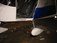
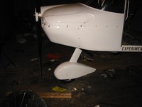
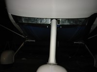
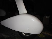
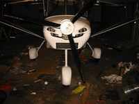
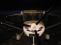
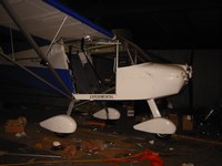
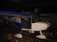
OK, today I had my brother with me to help me drop the nose wheel strut. I wanted to grease the strut and put the wheel pants (spat) on the nosewheel. With my brother holding the tail all the way to the ground, I banged the strut out with a hammer. It came out without too much effort. I put the wheel pant and struct fairing on, put white lithium grease on the section that is held by the frame and attempted to slide the strut back in place. Wow this was hard! It took about an hour for us to get the strut all the way back through, twisting, banging, twisting, banging. Tip: a rubber mallet works great, just hammer away at the bottoms of the fork, once I found this technique, things started to go quickly. The manual says to rivet the wheel pant to the fork, so with the help of my brother I aligned and sighted the wheel pant, then riveted it through the pre-drilled holes on the outsides of the fork. Next I cut a template for the main gear wheel pants. This template allowed for the brake caliper top mounting bolt and also enough open space for the stainless steel braided brake line to pass through. These went fast, using a sheet metal cutter to make the side vertical cuts. I actually made several parallel cuts inside the side cuts and simply broke the individual strips at the top to create a rough horizontal break. Next, I used the dremel to shape the top and dress up the vertical cuts. I had prevoiusly made the wheel pant supports for the outside of the wheels, these are simply aluminum tubes with 'L' brackets bolted on them. They protrude from the wheel enough to keep the wheel pant from striking the wheel. I fitted the wheel pants and took a few pictures. The plane actually looks a lot better with them on in my opinion.
|
|
5/08/06 (5 hours)
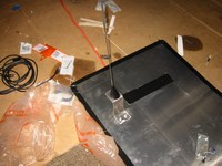
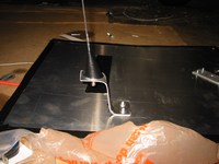
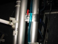
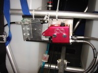
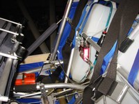
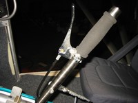
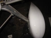
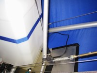
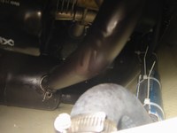
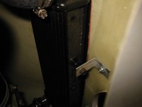
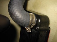
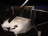
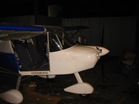
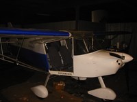
It's monday night. I decided to do the few small things that remain to be done on the plane. The ELT antenna needs to be mounted, but it needs a groundplane also (similiar to the VHF antenna). The ELT antenna is usually placed on the top of the aircraft whereas the VHF antenna is normally placed below, so I had an idea, I'll just mount it on the top of the VHF groundplane. Next, I fashioned a bracket for the fuel shutoff valve and riveted it to one of the lower cabin tubes. Next, I replaced the Oil Tank U-Bolt nuts with nylock versions. I glued velcro to the carpet sides to secure them agains falling on the occupants legs. Then I ran the brake lines and filled the system. I decided to temporarily mount the master cylinder plate with cable ties between the seats above the flap handle. I like this location and it's not being used for anything else, it allows easy access to the master cylinder also. After filling the system I tested the effectiveness of the new brake system. Well, it seems that the limited stroke of the brake lever is really hampering this setup. The brakes are now as good as they ever were on the original system but they have so much more potential. I will drill a lower hole in the master cylinder lever to create the effect of a longer stroke, then I'll see how much more effective this system is!! My plane is just about complete, the only thing left to do is Placarding (or labeling)!
|
|
5/09/06 (2 hours)
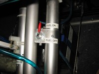
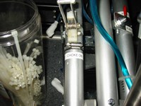
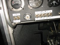
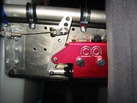
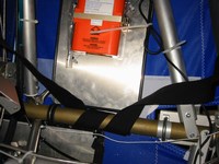
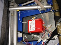
Tonight I just wanted to get the brakes working better. I first, bled the pilot side caliper because I thought that my initial installation process had a flaw in it. Next I drilled a hole lower on the master cylinder lever to give the hand lever more effective travel. This last step turned out to be a bad move, as I squeezed the lever I could see that the mechanical advantage was no longer there, the master cylinder lever would get to a point then the aluminum angle holding the cable would start to bend, also the brake lever attachment would start to bend. All this and the brakes were weaker than before. So I reconnected the brake cable back to the original hole in the master cylinder lever, and WOW! The braking power is better than it has ever been! It almost locks up the wheels! Conclusion: the pilot side brake line had air in it, and the brake lever itself is still the limiting factor in the brake system's effectiveness. I decided to do some placarding and some cleaning up of the wiring. All I have left to do is placard the airspeed indicator with colored arcs and the plane will be done!
|
|
5/10/06 ( hours)
OK, I found the suggest airspeeds in the UK flight manual for the SkyRanger, they are as follows:
| Vs0 (stall speed with flaps extended) | 33knots = 38mph (start of white arc) |
| Vs1 (stall speed with flaps retracted) | 36knots = 41mph (start of green arc) |
| Vx (best angle of climb) | 45knots = 51mph |
| minimum sink speed | 50knots = 57mph |
| Vy (best rate of climb) | 53knots = 61mph |
| approach speed | 55knots = 63mph |
| best glide speed | 60knots = 69mph |
| Vfe (maximum flaps extended speed) | 71knots = 81mph (end of white arc) |
| Va (manoeuvring speed (no abrupt control movements above this speed)) | 72knots = 82mph |
| Vno (strutural crusing speed (exceed only in smooth air)) | ?knots = ?mph (end of green arc, start of yellow arc) |
| Vne (never exceed speed) | 108knots = 124mph (end of yellow arc, red mark) |
It seems that Vno isn't given in the manual. I'll have to assign a reasonable value here in order to mark the speed with the transition of the green arc to the yellow arc. Let's be conservative and stay near Va, how about 78 knots or 90mph.
|
|
5/10/06 (4 hours)
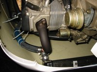
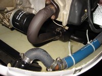
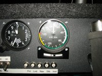
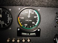
I had a friend come over to help me placard the airspeed indicator. My big bulky hands made it a real pain to try to place those little stickers on the instrument. Her smaller hands are perfect for the job
|
|
5/15/06 (2 hours)
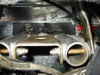
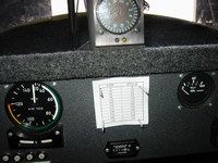
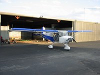
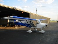
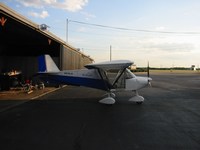
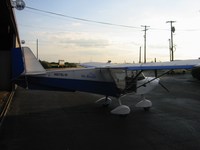
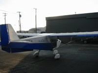
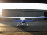
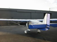
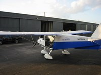
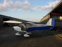
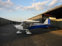
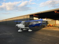
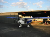
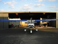
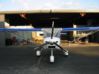
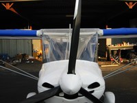
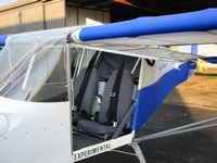
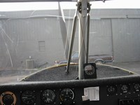
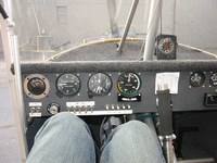
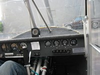
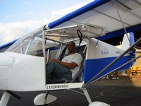
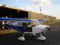
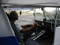
I was reading the Inspection Checklist on the EAA Homebuilders site and it mentioned something about checking for a Compass Card. I researched this subject and found that I must have a Compass Card (correction card) near the magnetic compass. The means of creating this card is called "Swinging the Compass" more on that when I find out how I'm going to do that. So today I decided to remove the Vertical Compass from its current position and place it on the dashboard, I'll cover the hole with the compass card. I'm thankful to move the Vertical Compass because the Hobbs meter (that instrument under the compass that records the length of time the power is turned on) would cause it to bounce whenever it ticked over. In it's new location it is completely unaffected by the Hobbs meter and any other eletrical systems. I decided to just take some pictures of the plane outside the hangar for the first time in a long time.
|
|
5/18/06 (4 hours)
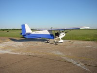
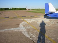
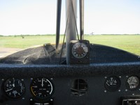
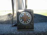
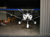
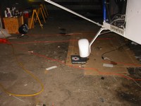
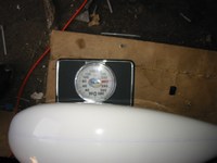
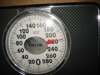
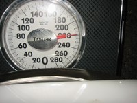
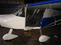
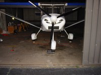
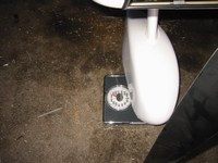
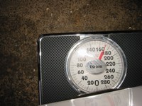
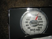
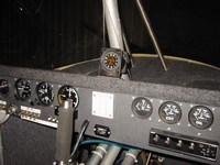
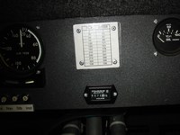
I had to take a friend to the commercial airport at 6:00 this morning so I decided it would be a great time to go "Swing The Compass"! "Swinging the Compass" is the process of determining the error the magnetic compass reads in the plane. It will read a slight error due to the metal around it, electrical instruments, and engine electrical systems. The idea is to find a "Compass Rose" (basically a large accurate ground painting of a magnetic compass, found on most airports), position the plane through 30 degree points, start the engine and note the difference in what the compass on the ground says and what the compass in the plane says. Previously, I searched Google Earth for Dallas Executive Airport to get a satellite view of the airport, and I found the "Compass Rose". It looked a little worn on Google Earth but it's data tends to be a few years old. I was hoping that the "Compass Rose" had been repainted along with all the other modifications they are making to the airport. That morning I did indeed find the "Compass Rose" where Google Earth said it would be, however, it was even more worn than Goolge Earth had shown, and some of it had been removed altogether. Only a few of the points were actually useable, so I had to do my best to position the aircraft straight. This was a fun process, get out turn the aircraft by pushing down on the tail which lifts the nose, and turn it into position, then get in start the engine and read the compass. I did this for 8 points, as the compass only had 8 points instead of the 12 that I needed. I determined the other 4 by assigning them the same error I got from the closest point in that particular quadrant. The errors were mostly plus or minus 1. Later that night, after work, I decided to weigh the plane in order to do weight and balance calculations. Using my grandmothers bathroom scale:-), the passenger wheel weighed in at 216lbs, the pilot wheel at 218lbs, and the nose wheel came in at 172lbs for a total empty weight of 606lbs.
|
|
5/20/06 (1 hour)
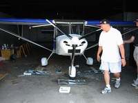
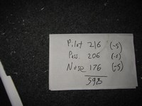
The EAA Chapter that I am a part of has an actual weighing system for aircraft. This system consist of 3 modified bathroom scales and 3 ramps that the aircraft's wheels are rolled onto. The ramps also act as levers to reduce the weight reading by a factor or 2 or 4. Thus you can weigh a plane that weighs 1000lbs at one wheel and that scale will read only 250lbs (1000/4). This gives the club the capactiy to weigh the RV's that make up the majority of the aircraft. To weigh my plane we used the ramps at the factor of 2 setting. Thus we had to multiply the scale readings by 2 to arrive at the actual weight, also we had to subtract 5lb to compensate for the weight of the ramps themselves. Also the guys brought up a point I hadn't thought of, you must level the plane to weigh it properly. The correct leveling points for the SkyRanger seems to be the leading edge and trailing edges (forward of the elevator) of the horizontal stablizer with a 10mm spacer added to the trailing edge. The weights came out as follows: 216lbs for the pilot wheel, 206lbs for the passenger wheel, and 176lbs for the nose wheel for a total of 598lbs.
|
|
5/19/06
WEIGHT and BALANCE.
| ITEM | WEIGHT (lbs) | ARM (in) | MOMENT (weight * arm) |
| Pilot Wheel | 216 | 28 | 6048 |
| Passenger Wheel | 206 | 28 | 5768 |
| Nose Wheel | 176 | -28 | -4928 |
| | | | |
| 14gal Fuel (6.25lbs/gal) | 88 | 42 | 3696 |
| Pilot | 185 | 20 | 3700 |
| Passenger | 150 | 20 | 3000 |
| Pilot/Passenger(@240) | 240 | 20 | 4800 |
| Pilot/Passenger(@250) | 250 | 20 | 5000 |
| Baggage | 50 | 45 | 2250 |
| Baggage(@45) | 45 | 45 | 2025 |
| Aircraft Loading Configuration | Total Weight (lbs) | Total Moment | CG = Moment/Weight |
| Empty Aircraft | 598 | 6888 | 11.52 |
| Pilot | 783 | 10588 | 13.52 |
| Pilot + max Fuel | 871 | 14284 | 16.40 |
| Pilot + Pass + max Fuel | 1021 | 17284 | 16.93 |
| Pilot + Pass + max Fuel + Baggage | 1071 | 19534 | 18.24 |
| Pilot + Pass(@185) + max Fuel | 1056 | 17984 | 17.03 |
| Pilot(@250) + Pass(@250) + max Fuel | 1186 | 20584 | 17.36 |
| Pilot(@240) + Pass(@240) + max Fuel + Baggage(@45) | 1211 | 22209 | 18.34 |
CG Limits: 9 to 19 inches from datum point (Leading Edge of Wing)
Maximum Weight: 1212lbs
|
|
5/21/06 (1 hour)
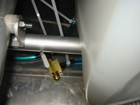
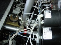
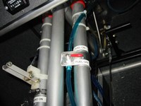
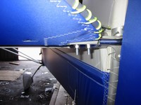
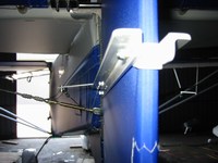
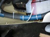
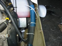
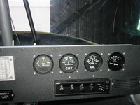
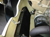
The EAA techincal counselor came over and did the third and final techinical inspection today. He said everything looked great and that I am ready for the actual airworthiness inspection. He did list a few items to look at improving and I still have a few final items to do:
1) Secure long water hose from vibrating (I can do this with a tie wrap to one of the cowling nuts)
2) Trim radiator bracket edges so no one can cut themselves
3) Cut all tie wraps flush to remove cutting surfaces
4) Reduce the aileron control forces (maybe lubricate the control stick bearing)
5) Place red markings on max CHT and Oil Temp
6) Cut down elevator bolts
7) Verify that fuel selector cannot be inadvertently activated by the passenger pant leg (I may have to reverse the orientation of the valve)
8) Tie wrap sensor connection so they don't vibrate loose
9) Torque and safety wire propellor bolts
|
|
5/25/06 (2 hours)
Tonight I finished up a lot of the things that the technical counselor indicated that I needed to do. I secured the radiator hose to the cowling so that it will not vibrate, I trimmed the radiator brackets, I cut the elevator bolts down to reasonable lengths, reversed the fuel selector so that it points inside in order to cut off fuel flow (this cannot be done inadvertingly), tie wrapped sensor connections, and finally torqued and safety wired the prop bolts to 200 in/lbs (or 16.667 ft/lbs) with a torque wrench. I also changed the throttle handles a bit so they look cooler, and the won't be mistaken for handles when passengers get in the plane:-) (a tip given to me by one of the hangar workers). I still need to put markings on the Oil Temp, Oil Press, and CHT gauges. Also I need to trim all tie wraps. The aileron forces seem to be OK now since I oiled the control stick bushing, so I won't worry about that.
|
|
5/26/06
I received the paper work from the DAR today and began working on it. I also received a call from him saying he would be in the area next Thursday (06/01/06) and could do the inspection then. I am pumped, ready to get my airworthiness certificate, so I told him that I can have the paperwork ready by then!! Here is the paper work that needs to be done:
1) 8050-3 Form - This is the actual registration certificate that is sent to you by the FAA, I received mine on 04/03/06 after sending in the 8050-1 form, 8050-88 form, and reserving an N number online. Make sure these forms are absolutely correct (read very very carefully), in my haste I made mistakes and these were sent back to me twice for corrections, by mail, very frustrating. My advice is to seek out advice from a DAR for all paperwork (even registration and N number request) before sending it in.
2) Program Letter - letter requesting inspection and flight test area and limitations if any
3) 8130-6 Form - Application for Airworthiness Certificate
4) 8130-12 Form - Eligibility Statement Amateur Built Aircraft - this needs to be notarized
5) Drawings or Photographs of the plane
6) Weight and Balance calculations
7) Construction Log with technical inspections
|
|
5/31/06 FAA INSPECTION!!
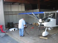
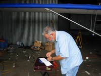
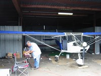
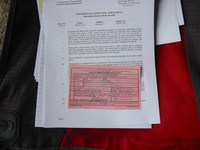
The DAR came by today to do the actual FAA Inspection. The inspection went extremely well, it lasted about 2 hours. The only item to change is the Passanger Warning card, it currently reads "Light-Sport Aircraft" but needs to read "Amateur-Built aircraft". I didn't realize there were two forms of Passanger Warning cards out there. OK I need to order this from LEAF (Leading Edge Airfoils) or Aircraft Spruce before I can fly. Also I need to get my transponder installation certified. As luck would have it, a transponder technician (Paul) works a few hangars down. Anyway, I GOT MY AIRWORTHINESS CERTIFICATE!!! I now have to begin a 40 hour testing period that requires that I fly only within a 35nm radius of the airport and stay out of class B airspace. Normally the restriction is a 25nm radius but because the DFW class B airspace takes up half that area, the DAR saw fit to extend the area a bit. After the 40 hour testing period I can have passengers and fly wherever I want! STAY TUNED!! FIRST FLIGHT VIDEO TO COME!
|
|
6/23/06 FIRST FLIGHT!!
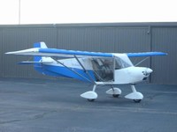
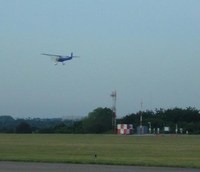
Early in the morning of Friday June 23, 2006 I awoke and headed to the airport. I wanted to make it to the airport before the helicopters began flying. I figured that they would not begin flying before the tower resumed operation at 8:00am so I aimed to takeoff at 7:15am. I got to the airport around 6:30am and began an extensive pre-flight check. I was waiting on my parents to arrive, when I heard the sound of piston powered helicopters starting up. It was just 7:10am when these guys started flying around. They tend to just hover around the runways which is the reason I didn't want them around on this day. But I can work with this. My family arrived and I gave them a quick clinic on how to use the cameras and camcorders. Then around 7:20 I started N876LW and taxied to the runway. On the radio I could hear the helicopters, one was doing a right-hand pattern. I radioed to them to let them know that I was in an experimental aircraft and will be flying it for the first time, I told them that I would like to do a standard left-hand pattern. They agreed and said they would stay out of the way and watch out for me. So I did a quick runup and headed to the runway centerline. I wanted to allow my family to get a picture of me as I lifted off so I began a long takeoff run. This was good and allowed me to pay more attention to the aircraft as it slowly accelerated. As I neared the point where my parents were I throttled all the way up. N876LW leapt into the air with a fairly strong left-roll tendency that I had to correct for with ample right aileron. The engine was strong and I throttled back to reduce the climb rate and put the nose back to a flatter attitude. I climbed out fairly quickly and only climbed to 600ft above the airport keeping a relatively tight pattern. The crosswind, downwind, and base legs were fairly uneventful, I just had to maintain the right aileron input. I checked the gauges quickly and noticed I had been flying around 70mph the entire flight. On final I did not deploy the flaps and decided to just leave them up. N876LW was extremely easy to land even though my approach speed was high, it bled off airspeed nicely once I was over the runway. I landed softly at the end of the runway and had to taxi quite a ways up to get to the turnoff point near my family. I taxied to the hangar and shut off the engine. Congratulations were in order for my Successfull First Flight!!! I watched the video later and it is a bit shakey since my dad didn't have a tripod. I'll get it posted soon. So after a documented 215 hours build time (probably closer to 250 actual thinking/building time) I have a flying aircraft and I have started flying off the 40hrs of flight testing time!!
|
|
8/24/06 VIDEOS (FINALLY)!!
First Flight Videos
First Flight Starting Engine(2Mb)
First Flight Taxiing(3Mb)
First Flight Takeoff(3Mb)
First Flight Landing(1Mb)
These first flight videos are kinda shaky, so that's not turbulence that's just the camera shaking:-)
Third Flight Videos
Third Flight Camera-In-Plane 1(8Mb)
Third Flight Camera-In-Plane 2(8Mb) (check out the yaw on takeoff)
Third Flight Camera-In-Plane 3(8Mb) (first touch-and-go near end)
Third Flight Camera-In-Plane 4(8Mb)
Third Flight Camera-In-Plane 5(8Mb)
Third Flight Camera-In-Plane 6(8Mb)
These videos are from my camera which I mounted in the plane near the rear of the roof. I was just doing pattern work that day so these videos show 4 touch-and-goes.
|
|